
Vacuum circulative radiating system for electric driver of electric vehicle

A motor driver and heat dissipation system technology, applied in the field of electric vehicles, can solve the problems of low heat dissipation efficiency, inability to reduce the machine to ambient temperature or below, and inability to cope with the heat dissipation requirements of power equipment, so as to achieve heat dissipation and prolong service life. , the effect of reducing the conditions of use

Inactive Publication Date: 2012-02-22
孙建章 +2
View PDF5 Cites 2 Cited by
  • Summary
  • Abstract
  • Description
  • Claims
  • Application Information

AI Technical Summary

Problems solved by technology

This heat dissipation method cannot effectively reduce the heat inside the high-power power supply equipment in a timely manner.
If the ambient temperature is very high in summer, although this form of radiator can be improved, it still cannot meet the heat dissipation requirements of the current power supply equipment with increasing power.
[0007] From the perspective of heat dissipation principle, this type of radiator is passive heat dissipation, the heat dissipation efficiency is not high, and it cannot fundamentally reduce the temperature inside the machine to the ambient temperature or below the ambient temperature.

Method used


Image

  • Vacuum circulative radiating system for electric driver of electric vehicle
  • Vacuum circulative radiating system for electric driver of electric vehicle

Examples


Embodiment Construction

[0017] The technical solutions of the present invention will be described in detail below in conjunction with the accompanying drawings.

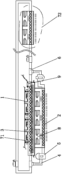
[0018] like figure 1 As shown, the present invention provides a vacuum cycle heat dissipation system for electric vehicle motor drivers, including an intelligent control circuit 1, a condenser 2, a heat insulation layer 3, a refrigerant pipeline 4, a variable speed compressor 5, a three-way solenoid valve 6 and two evaporators 71, 72, wherein, the heat-absorbing surface of the evaporator 71 is attached to a high-power heating device, and the heat-absorbing surface of the evaporator 72 is arranged in the compartment; The heat-dissipating surface, the other side is in contact with the heat-absorbing surface of the condenser 2; the refrigerant pipes 4 are respectively distributed between the heat-insulating layer 3 and the heat-dissipating surfaces of the two evaporators 71 and 72, and the internal movement of the refrigerant is used to fully...


PUM


Abstract

The invention discloses a vacuum circulative radiating system for an electric driver of an electric vehicle. The vacuum circulative radiating system comprises two evaporators, a three-way electromagnetic valve, an intelligent control circuit, a condenser, a heat insulating layer, cold medium pipelines and a variable-speed compressor, wherein the heat absorbing surfaces of the evaporators are attached to a high-power heating device and formed in a carriage respectively; radiating surfaces of the two evaporators are attached to one side of the heat insulating layer; the other side of the heat insulating layer is contacted with the heat absorbing surface of the condenser; the cold medium pipelines are distributed between the heat insulating layer and the radiating surfaces of the evaporators; the three-way electromagnetic valve is connected between the variable-speed compressor and the cold medium pipelines; and the intelligent control circuit is connected with the variable-speed compressor and the three-way electromagnetic valve, and is used for adjusting the on / off of the cold medium pipelines on the evaporators respectively. By adopting the radiating system, radiating of the high-power heating device can be realized, the service conditions of components are lowered, and the service life of a product is prolonged; or the internal space of an automobile can be cooled simultaneously, and air conditioning and cooling effects are achieved.

Description

technical field [0001] The invention belongs to the field of electric vehicles, and in particular relates to a refrigerant intelligent vacuum circulation heat dissipation system used for cooling high-power heating components of electric vehicle motor drivers. Background technique [0002] Electric vehicles are a safe, economical and clean green means of transportation. They not only have their unique advantages and competitiveness in terms of energy and environment, but also can more easily adopt modern control technology to achieve the goal of mechatronics. Therefore, they have Broad development prospects. [0003] An electric vehicle is a road transport tool that uses electricity as an energy source, is driven by an electric motor, and uses its own power supply as the driving energy. A pure electric vehicle is a typical zero-emission vehicle. It does not burn fuel, has no exhaust gas from combustion, and has no pollutants such as coolant and engine oil. In the context ...

Claims


Application Information

Patent Timeline
IPC IPC(8): B60K11/04
Inventor 孙建章张福兴王伟
Owner 孙建章
Learn More