
Temperature protection circuit and method

A technology of temperature protection circuit and driving protection circuit, applied in the field of circuits, can solve the problems of incapable of intelligent and targeted protection measures, difficult to distinguish temperature changes, etc., and achieve the effects of easy system expansion, less misoperation, and stable work.

Inactive Publication Date: 2012-02-15
广东顺德盈派超科电子科技有限公司
View PDF2 Cites 2 Cited by
  • Summary
  • Abstract
  • Description
  • Claims
  • Application Information

AI Technical Summary

Problems solved by technology

This method has the following disadvantages: (1) the circuit is simple and prone to misoperation; (2) it is not easy to distinguish different temperature changes, so it is not possible to intelligently adopt targeted protection measures

Method used


Image

  • Temperature protection circuit and method
  • Temperature protection circuit and method
  • Temperature protection circuit and method

Examples


Embodiment Construction

[0027] In order to make the technical means, creative features, goals and effects achieved by the present invention easy to understand, the present invention will be further described below in conjunction with specific diagrams.

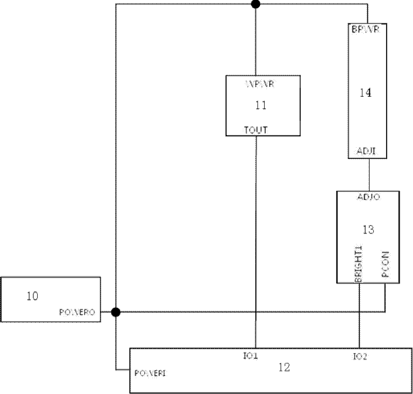
[0028] refer to figure 1 , a temperature protection circuit, comprising a detected unit 14, the detected unit 14 is provided with a temperature detection module 11, the signal output end of the temperature detection module 11 is connected to an intelligent control module 12, and the signal output end of the intelligent control module 12 is connected to a The driving protection circuit 13 controls the detected unit 14 through the driving protection circuit 13 . Here, the drive protection circuit 13 can be a dedicated protection circuit or an adjustable function circuit of the detected unit, or the detected unit 14 is connected to a drive circuit, and the drive protection circuit 13 can be a protection circuit of the drive circuit or a drive circuit ....


PUM


Abstract

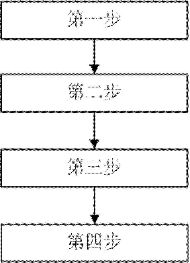
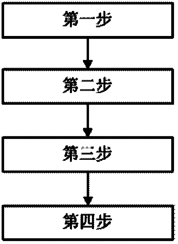
The invention relates to the technical field of circuits, and in particular relates to a temperature protection circuit and method. The temperature protection method comprises the following steps of: step one, providing a direct current power supply by a power supply module; step two, detecting the temperature of a detected unit by a temperature detection module, and outputting electrical signals to an intelligent control module; step three, analyzing the electrical signals output by the temperature detection module by the intelligent control module in accordance with a temperature limit value or adjustment rules in a fault mode static state database or dynamic database with a self-directed learning mode, and outputting the electrical signals to a driving protection circuit; and step four, outputting corresponding electrical signals to the detected unit by the driving protection circuit, so that the detected unit can adjust the working state. According to the invention, error actions are difficult to occur, the operation is stable, different temperature change phenomena can be differentiated, reasonable and effective protection measures are took, the stable operation of the system can be ensured, and the system expansion can be realized conveniently.

Description

technical field [0001] The invention relates to the technical field of circuits, in particular to a temperature protection circuit and method. Background technique [0002] In all kinds of equipment, the high working temperature of the components can easily lead to the failure of the components and even the damage of the equipment. Current circuit protection methods mainly use a detection circuit composed of a thermistor or a temperature detection chip to detect the temperature of the detected unit, and activate the protection circuit when the temperature exceeds or falls below a preset value. This method has the following disadvantages: (1) the circuit is simple and prone to misoperation; (2) it is difficult to distinguish different temperature change phenomena, so targeted protection measures cannot be intelligently adopted. Contents of the invention [0003] The object of the present invention is to provide a temperature protection circuit to solve the above technical ...

Claims


Application Information

Patent Timeline
Patent Type & Authority Applications(China)
IPC IPC(8): H02H5/04
Inventor 林志一辜长明李增光张艳李玉梅李力健
Owner 广东顺德盈派超科电子科技有限公司
Learn More