Aligning apparatus

A technology for centering and screw adjustment, which is applied to parts and instruments of instruments, etc. It can solve the problems of long time for centering and difficult control of centering precision, and achieve the advantages of preventing local deformation, shortening time for centering, and accurate fine-tuning position Effect

Active Publication Date: 2014-12-24
CHINA AVIATION POWER MACHINE INST
View PDF4 Cites 0 Cited by
  • Summary
  • Abstract
  • Description
  • Claims
  • Application Information

AI Technical Summary

Problems solved by technology

[0008] The purpose of the present invention is to provide a centering device to solve the technical problem in the related art that the centering accuracy is difficult to control and thus the centering takes a long time

Method used


Image

  • Aligning apparatus
  • Aligning apparatus
  • Aligning apparatus

Examples


Embodiment Construction

[0023] The embodiments of the present invention will be described in detail below with reference to the accompanying drawings, but the present invention can be implemented in many different ways defined and covered by the claims.

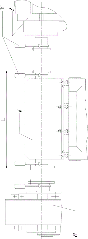
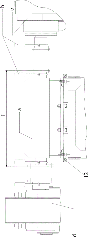
[0024] figure 2 It is a schematic diagram of the centering device according to the preferred embodiment of the present invention, a is the device to be centered (it may be a torque loader), b is the laser centering instrument, c and d are the fixed parts at both ends respectively.

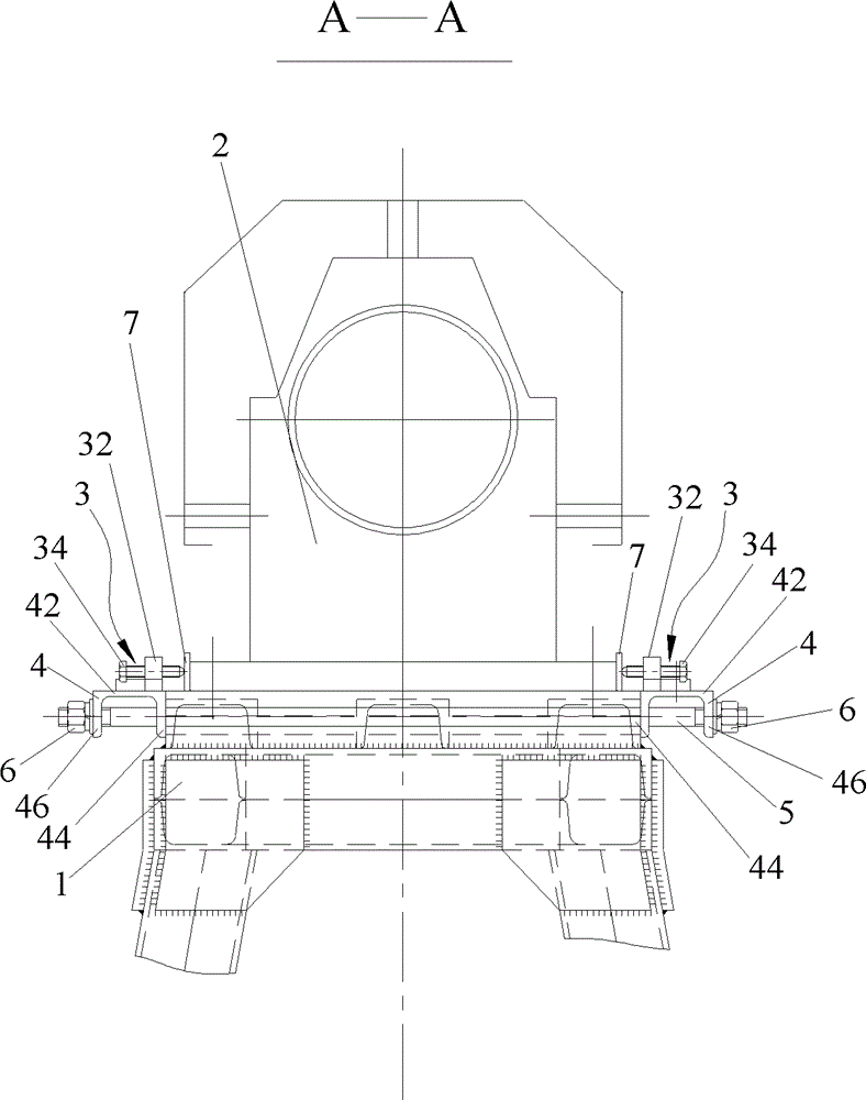
[0025] image 3 It is a side view structural schematic diagram of the centering device according to the preferred embodiment of the present invention. see figure 2 and 3 , according to the aligning device of the present invention, comprising a support 1 for supporting the components 2 to be aligned, the support 1 has a first end 12 and a second end 14 along the axial direction of the components 2 to be aligned , wherein, the two ends of the first end portion 12 and...


PUM


Abstract

The invention provides an aligning apparatus which comprises a bearer (1) used for supporting a part (2) to be aligned. The bearer has a first end (12) and a second end (14) along an axial direction of the part (2) to be aligned. Positions of two ends of the first end (12) and the second end (14) or positions next to the two ends are provided with adjusting mechanisms (3) respectively. The apparatus also comprises clamping rooting parts (4) which are provided at the positions of the two ends of the first end (12) and the second end (14) or the positions next to the two ends, and the adjusting mechanisms (3) are provided on the clamping rooting parts (4). A key point of the present invention is arranging the clamping rooting parts and employing four screw fine tuning positions. According to the invention, the screw fine tuning positions are employed, thus impact force mentioned in related technology is not existed, and stepless adjusting can be carried out.

Description

technical field [0001] The invention relates to a centering device. Background technique [0002] Some mechanical closed testers usually contain two closed loops. If a test is to be carried out in one of the loops, the torque loader needs to be moved into the closed loop. However, when the closed circuit is replaced, the loader needs to move position accordingly, and every time the position is shifted, the coaxiality between the two output flanges of the loader and the adjacent fixed parts at both ends needs to be readjusted. [0003] figure 1 It is a schematic diagram of the centering device in the prior art. see figure 1 , the torque of the loader a' is output by the flanges at both ends, and the two flanges are located on the same axis. Here, centering usually adopts laser centering instrument b'. Due to the left and right fixed parts (see figure 1 There is also incomplete concentricity between c' and d') (that is, the axes of the two are within a certain coaxiality...

Claims


Application Information

Patent Timeline
Patent Type & Authority Patents(China)
IPC IPC(8): G12B5/00
Inventor 夏海纯
Owner CHINA AVIATION POWER MACHINE INST
Why Eureka
Try Eureka