Peak voltage digital display meter
A peak voltage and digital display meter technology, which is applied in the field of voltage pulse peak measurement devices, can solve the problems of low precision and small measurement range, and achieve the effects of wide application range, automation and intelligence, and high measurement accuracy
- Summary
- Abstract
- Description
- Claims
- Application Information
AI Technical Summary
Problems solved by technology
Method used
Image
Examples
Embodiment 1
[0044] The measured peak voltage is between 1mv and 10mV.
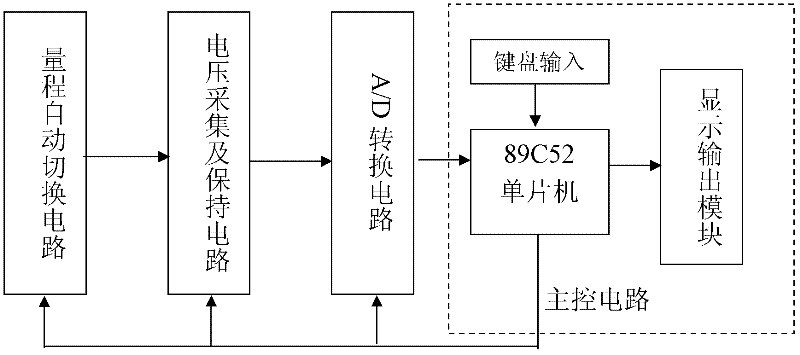
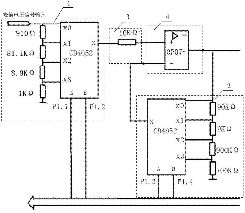
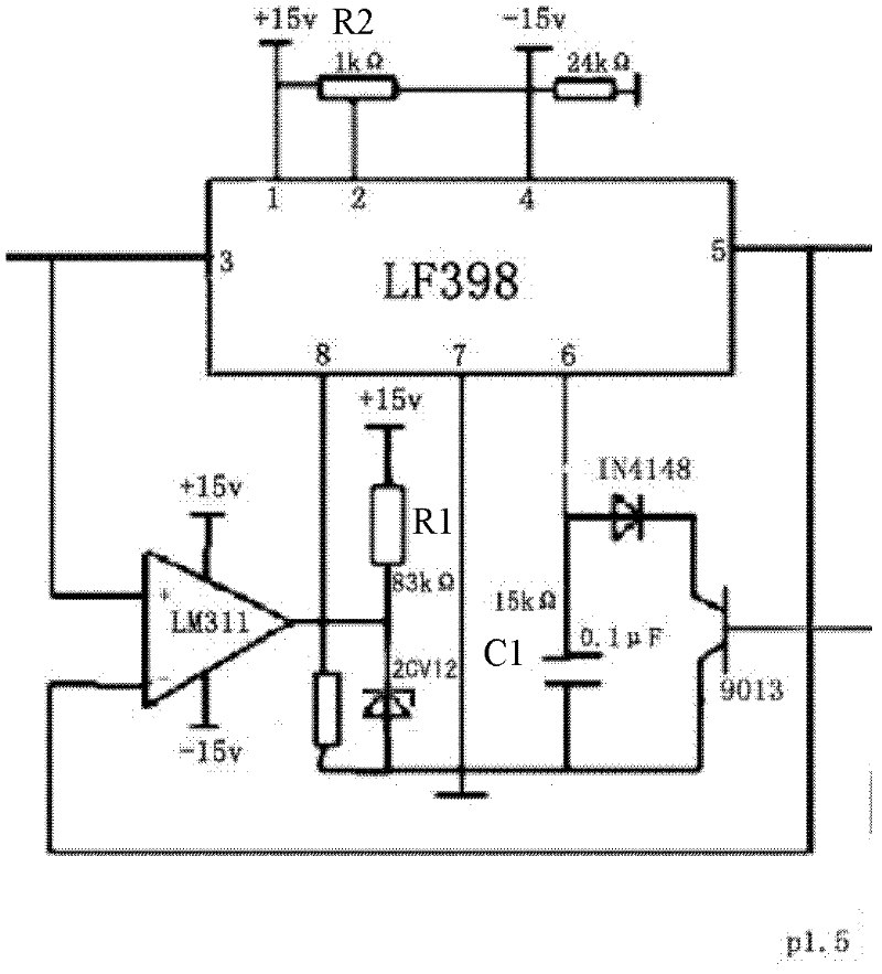
[0045] Press the power switch 8, turn on the power, the 89C52 single-chip microcomputer is initialized, and the automatic range switching circuit will automatically select ①1mv~10mv in the range selection button 9, at this time, the P1.1 and P1.2 pins of the 89C52 single-chip microcomputer send a low level , X0 of CD4052 double four-choice multi-way switch I 1 is directly connected to X, P1.3 and P1.4 pins of 89C52 MCU send high level, X of CD4052 double four-choice one multi-way switch II 2 is connected to X3 , CD4052 double four selection one multi-way switch II 2 voltage divider resistor 3 and OP07 operational amplifier 4 work together to achieve 1000 times amplification of the input voltage signal, and send the amplified voltage signal to the peak voltage acquisition and hold circuit, LF398 The output voltage and input voltage of the sample-and-hold device are compared by the LM311 voltage comparator. When the inp...
Embodiment 2
[0047] The measured peak voltage is greater than 10mv to 100mV.
[0048] In addition to pressing the power switch 8 and turning on the power supply, the 89C52 single-chip microcomputer is initialized, and the automatic range switching circuit will automatically select the ②10mv~100mV in the range selection button 9. At this time, the P1. Ping, X0 and X in the control multi-way switch I 1 are directly connected, the P1.3 pin of the 89C52 microcontroller sends out a high level, and the P1.4 pin sends out a low level, and the X and X2 in the control multi-way switch II 2 are connected, The voltage dividing resistor 3 of the CD4052 double four-select one multi-way switch II 2 and the OP07 operational amplifier 4 realize the 100-fold amplification of the input voltage signal under the joint action, and other operations and measurement processes are the same as in the embodiment 1.
Embodiment 3
[0050] The measured peak voltage is between greater than 100mv and 1V.
[0051] In addition to pressing the power switch 8 and turning on the power supply, the 89C52 single-chip microcomputer initializes, and the automatic range switching circuit will automatically select ③ 100mv~1V in the range selection button 9. At this time, the P1. Ping, X0 and X in control multi-way switch I 1 are directly connected, P1.3 of 89C52 MCU sends out low level, P1.4 pin sends out high level, X and X1 in control multi-way switch II 2 are connected, CD4052 double The voltage dividing resistor 3 of the four-select-one multi-way switch II 2 and the OP07 operational amplifier 4 work together to realize the 10-fold amplification of the input voltage signal, and other operations and measurement processes are the same as those in Embodiment 1.
PUM
 Abstract
Description
Claims
Application Information
 - R&D Engineer
- R&D Manager
- IP Professional
- Industry Leading Data Capabilities
- Powerful AI technology
- Patent DNA Extraction
Browse by: Latest US Patents, China's latest patents, Technical Efficacy Thesaurus, Application Domain, Technology Topic, Popular Technical Reports.
© 2024 PatSnap. All rights reserved.Legal|Privacy policy|Modern Slavery Act Transparency Statement|Sitemap|About US| Contact US: help@patsnap.com


