
Foam plane-making machine capable of feeding air at two ends

A sheet and foam technology, applied in the direction of flat products, household appliances, other household appliances, etc., can solve the problems of reducing product quality, energy waste, low steam utilization rate, etc., to improve work efficiency, reduce consumption, and improve utilization rate Effect

Active Publication Date: 2012-02-15
HANGZHOU FUYANG DONGSHAN PLASTIC MACHINERY
View PDF5 Cites 1 Cited by
  • Summary
  • Abstract
  • Description
  • Claims
  • Application Information

AI Technical Summary

Problems solved by technology

The structural design of this type of foam sheet machine is not reasonable enough, the overall layout is not scientific enough, and the steam is difficult to be evenly distributed into the mold cavity, resulting in uneven heating of the raw materials by steam, especially when the overall length of the foam sheet machine is long, such as foam When the length of the board machine is more than 6m, it is difficult to evenly distribute the steam into the mold cavity by means of air intake at one end, which not only affects the working efficiency of the foam board machine, but also greatly reduces the quality of the manufactured foam board, and makes Steam is difficult to be used effectively, resulting in waste of energy, which is not conducive to energy saving and environmental protection
[0004] For example, the publication date is June 11, 2008, and the publication number is CN201070824 in the Chinese patent, which discloses a foam sheet molding machine, which consists of a frame, an air box, a door, a feed air gun, a door opening cylinder, The ejector oil cylinder, locking oil cylinder, steam inlet pipe, cooling pipe and universal top plate are composed. The two inner large surfaces of the air box are arc-shaped. With this structure, the number of particles in the center of the air box can be increased in advance, so that the surrounding of the plate The density is consistent with the center density, and the produced foam slabs will not have the phenomenon of central depression; however, the foam slabs produced by the foam slab forming machine have an arc-shaped structure, which requires cutting corners, resulting in waste of materials, and , the foam sheet molding machine has a structure with air intake at one end, and the structural design is not reasonable enough, so that the steam distribution in the foam sheet molding machine is not uniform enough. The steam at the end of the steam inlet is strong, and the steam at the end far away from the steam inlet is weak, which greatly Affects production efficiency and reduces the quality of foam boards
Another example is that the publication date is April 02, 2008, and the publication number is CN201042836 in the Chinese patent, which discloses a kind of EPS sheet forming machine. With the ventilation holes set on the cavity plate of the mold cavity, the movable bottom mold with ventilation holes, and the steam inlet and exhaust ports of each steam chamber, a partition is set in the four vertical steam chambers of the mold cavity, and the partition board A communication pipe with a valve is set between the main and auxiliary steam chambers formed on both sides of the main and auxiliary steam chambers; a vent hole is provided within a certain distance above the cavity plate of the auxiliary steam chamber; the EPS sheet forming machine is also a structure of air intake at one end, so that Uneven distribution of steam inside the mold cavity reduces the quality of the EPS sheet
In addition, the publication date is June 29, 2005, and the publication number is CN2706296. In the Chinese patent, a multi-chamber foam sheet molding machine is disclosed. The multi-chamber foam sheet molding machine includes an upper air chamber, a lower air chamber, The first rear air chamber, the first front air chamber; it also includes N rear air chambers, N front air chambers, and N grilles; the grilles divide the mold cavity into different heights to realize the production of different specifications on the same equipment products; where N is a positive integer; the multi-chamber foam sheet molding machine also has a structure of air intake at one end, which makes the steam distribution in the mold cavity not uniform enough and reduces the quality of the product
[0005] To sum up, the structure design of the existing foam sheet molding machines is not reasonable enough, the layout is not scientific enough, the steam utilization rate is low, and it is difficult to meet the requirements of energy saving and environmental protection; Low, the steam is difficult to evenly distribute into the mold cavity of the foam board forming machine, and the quality of the manufactured foam board is poor, which hinders the better development of the foam board industry

Method used


Image

  • Foam plane-making machine capable of feeding air at two ends
  • Foam plane-making machine capable of feeding air at two ends
  • Foam plane-making machine capable of feeding air at two ends

Examples


Embodiment Construction

[0037] The present invention will be further described in detail below in conjunction with the accompanying drawings and examples. The following examples are explanations of the present invention and the present invention is not limited to the following examples.

[0038] Example.

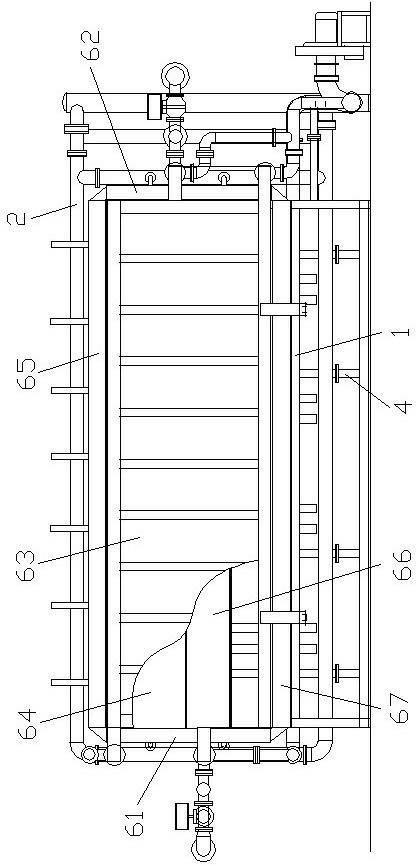
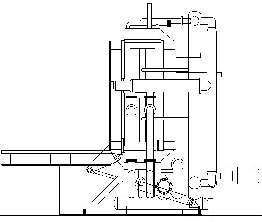
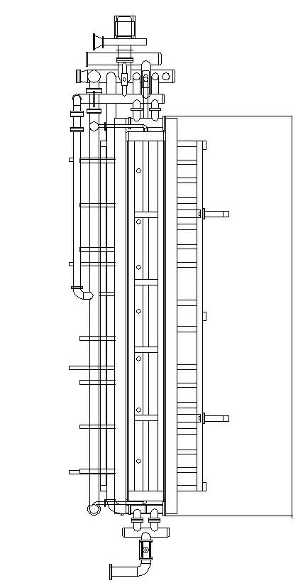
[0039] see Figure 1 to Figure 17 , the two-head air intake foam board machine in this embodiment includes a frame 1, a pipeline device 2, four sets of lifting devices 4, a left template 61, a right template 62, a front template 63, a rear template 64, a top template 65, an air Frame bottom formwork 66 and base plate 67, wherein, the number of sets of lifting device 4 among the present invention is at least one set of lifting device 4, the number of sets of this lifting device 4 can be set according to actual needs, and under normal circumstances, the quantity of this lifting device 4 can be Between 2-8 sets.

[0040] Left formwork 61 among the present embodiment, right formwork 62, front formwor...


PUM


Abstract

The invention relates to a foam plane-making machine capable of feeding air at two ends. A structure of the existing foam panel-making machine is not rational. The foam plane-making machine capable of feeding air at two ends comprises a frame, a pipeline device, a left formwork, a right formwork, a front formwork, a rear formwork, a top formwork and a bottom plate, and further comprises an air frame bottom formwork and at least a set of lifting device; the lifting device comprises a worm rod, a worm wheel, a flange, a lead screw, a lead screw sleeve and a sealing socket; the worm rod and the worm wheel are mounted on the frame, the sealing socket is fixed in a sealing hole on the bottom plate, one end of the flange is fixed on the worm wheel through the flange, the lead screw sleeve penetrates into the sealing socket; the pipeline device comprises a left formwork connecting pipe, a right formwork connecting pipe, a circular loop pipe, a left total steam inlet pipe, a rear formwork left connecting pipe, a front formwork left connecting pipe, a right total steam inlet pipe, a rear formwork right connecting pipe, a front formwork right connecting pipe, a top formwork right connecting pipe and an air frame bottom formwork right connecting pipe. The structure provided by the invention is reasonable in structure design, scientific in layout, energy-saving and environmentally-friendly and high in working efficiency.

Description

technical field [0001] The present invention relates to a foam board machine, in particular to a foam board machine with two air intakes, which is mainly used to manufacture foam boards. Steam is fed into both ends, which is conducive to a more uniform distribution of steam, which belongs to a kind of equipment for manufacturing foam boards. Background technique [0002] With the wide application of foam boards and the increasing usage, people have higher and higher requirements for the quality of foam boards, which makes foam board manufacturers put forward higher requirements for the equipment for manufacturing foam boards. At present, foam boards are mainly manufactured by foam board machines, which requires greatly improving the performance requirements of the foam board machines, so that reliable and high-quality foam boards can be produced. [0003] Existing foam board machines usually include a mold cavity for placing raw materials and a set of pipelines for supplyin...

Claims


Application Information

Patent Timeline
Patent Type & Authority Applications(China)
IPC IPC(8): B29C44/02B29C44/34B29L7/00
Inventor 徐元朝
Owner HANGZHOU FUYANG DONGSHAN PLASTIC MACHINERY
Learn More