
Roller processing machine

A technology for processing machine tools and rolls, which is applied to metal processing machinery parts, metal processing equipment, manufacturing tools, etc., can solve the problems of high technical requirements, difficulty in ensuring processing accuracy, and low work efficiency, and achieve accurate indexing and easy processing accuracy Guaranteed, efficient work

Inactive Publication Date: 2012-02-15
杨文风 +5
View PDF5 Cites 4 Cited by
  • Summary
  • Abstract
  • Description
  • Claims
  • Application Information

AI Technical Summary

Problems solved by technology

The work efficiency is low, the machining accuracy is not easy to guarantee, and the technical requirements for the processing personnel are relatively high

Method used


Image

  • Roller processing machine
  • Roller processing machine
  • Roller processing machine

Examples


Embodiment Construction

[0015] In order to further understand the invention content, characteristics and effects of the present invention, the following examples are given, and detailed descriptions are as follows in conjunction with the accompanying drawings:

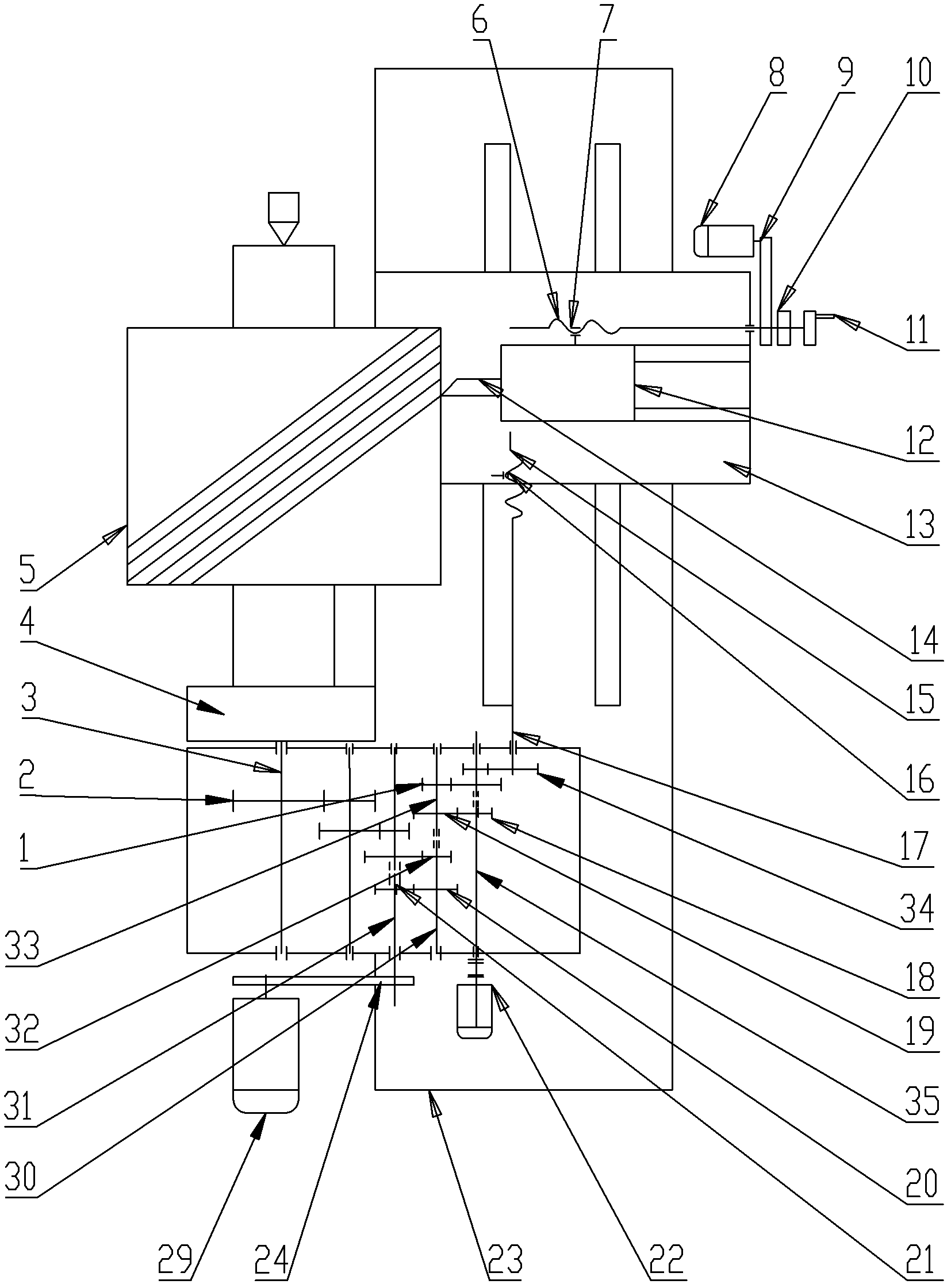
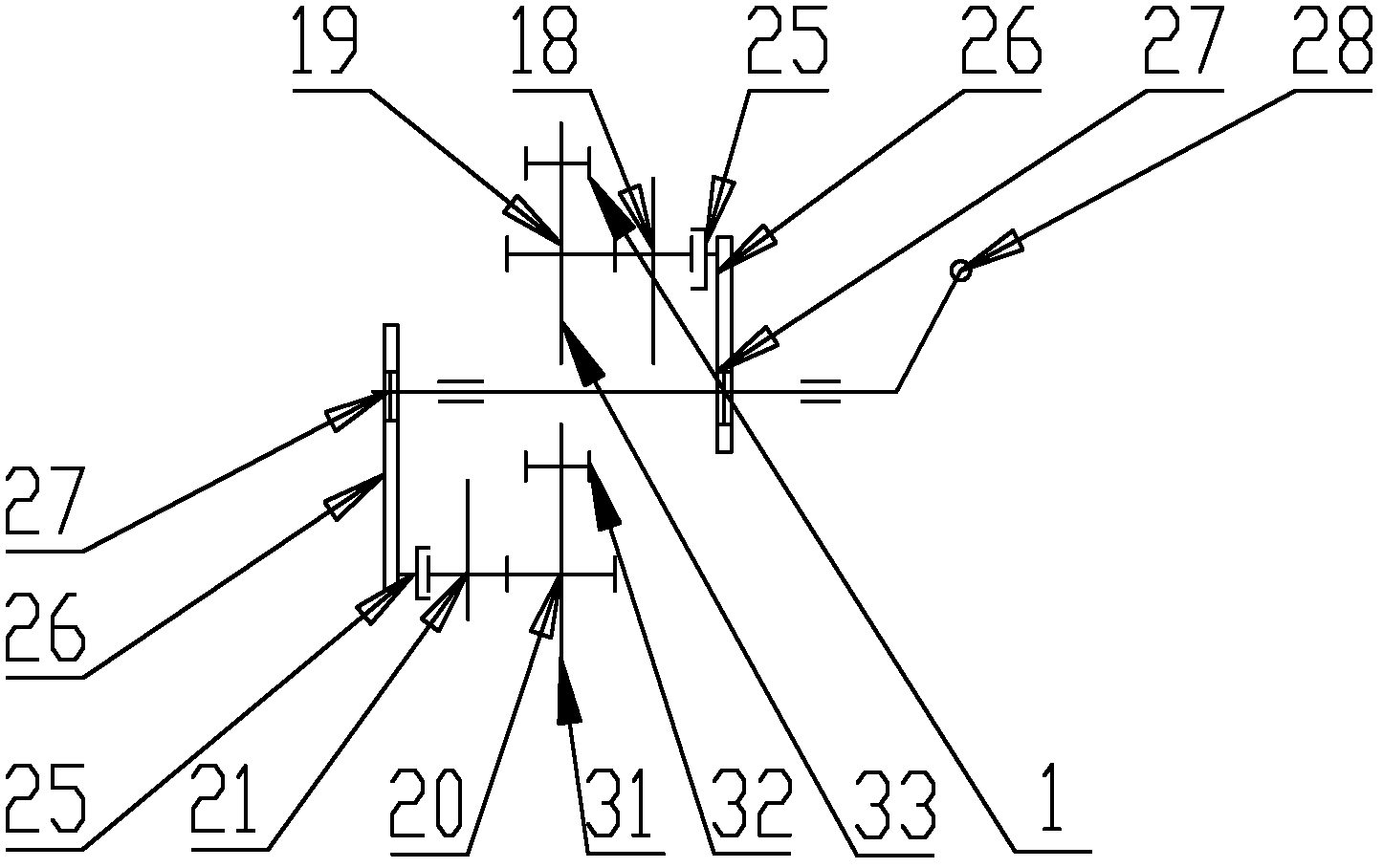
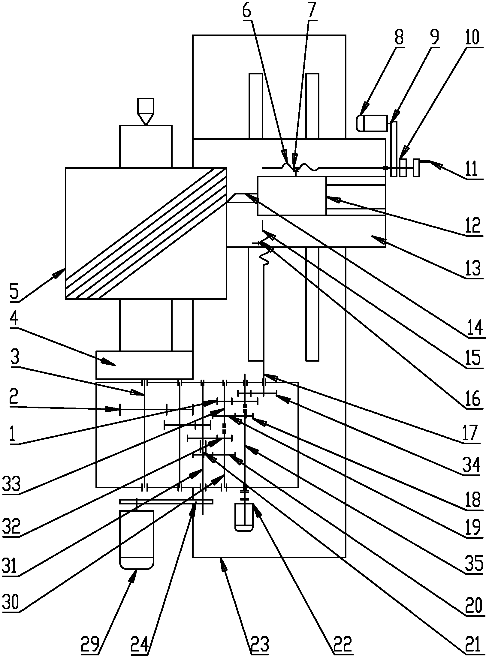
[0016] See Figure 1 ~ Figure 2 , a roll processing machine tool, including a turning tool radial feed mechanism and a gear box, the first input shaft 31, the second input shaft 35, the first output shaft 3 and the second output shaft parallel to each other are installed in the gear box Shaft 17 and coaxially arranged first transition shaft 30 and second transition shaft 33; said first transition shaft 30 is equipped with input gear A20 and transmission gear A32, and said transmission gear A32 drives the first transition shaft through the first gear transmission mechanism A gear 2, the first gear 2 is installed on the first output shaft 3, the workpiece chuck 4 is connected on the first output shaft 3; the input gear B19 and the second transi...


PUM


Abstract

The invention discloses a roller processing machine which comprises a turning tool radial feed mechanism and a gear box, wherein a first input shaft, a second input shaft, a first output shaft and a second output shaft which are parallel to each other and a first transition shaft and a second transition shaft which are coaxially arranged are mounted in the gear box; the first transition shaft is provided with an input gear A and a transmission gear A; the second transition shaft is provided with an input gear B and a transmission gear B; the first input shaft is connected with a first slidinggear; the second input shaft is connected with a second sliding gear; when the first sliding gear is meshed with the input gear A, the second sliding gear is meshed with the input gear B; and when the first sliding gear is meshed with the input gear B, the second sliding gear is meshed with the input gear A. Through the invention, the indexing is accurate, the processing precision is easily guaranteed, the working efficiency is high, and the energy consumption is low.

Description

technical field [0001] The invention relates to a special equipment for the rubber industry, in particular to a roll processing machine tool for a raw rubber rolling mill. Background technique [0002] Currently, in rubber plantations in Southeast Asia, the raw rubber collected contains sand and other debris. Removal of sand and other debris after curing is done on the rolling mill. There are two rolls on the rolling mill, and the rolls are provided with spiral grooves. When the rubber passes through the two rollers, the spiral groove cuts the rubber like scissors. Sand and other debris are exposed, and the water spray mechanism on the rolling mill washes the sand and other debris away. Clean rubber can be obtained by shearing and washing the rubber several times. The two rolls on the rolling mill are used for a period of time, and the spiral grooves are worn out and lose their shearing ability. At this time, the roll needs to be removed for reprocessing. Turning off t...

Claims


Application Information

Patent Timeline
IPC IPC(8): B23B5/08B23B19/00B23Q5/40
Inventor 曹金占王嘉琪
Owner 杨文风
Learn More