Positioning and clamping device for machining inclined hole in annular part and method of positioning and clamping device for machining inclined hole in annular part

A technology for positioning clamping and ring parts, applied in positioning devices, metal processing machinery parts, metal processing equipment, etc., can solve the problems of difficult to determine the indexing method, requirements for distance dimensions, errors, etc., so that it will not be easily rotated and fixed , The processing safety factor is improved, and the effect of meeting the processing requirements

Active Publication Date: 2020-09-25
AECC AVIATION POWER CO LTD
View PDF4 Cites 1 Cited by
  • Summary
  • Abstract
  • Description
  • Claims
  • Application Information

AI Technical Summary

Problems solved by technology

[0002] The nozzle is one of the parts of the engine. It is a ring. There are two bosses symmetrically arranged on the outer ring, and a ring groove is opened on the inner ring. Slanted holes are symmetrically arranged on the surface of the ring groove and the aforementioned inclined holes penetrate the bosses. The plane where the centerline of the inclined hole coincides with the plane where the centerline of the boss is located, and the distance between the centerline of the inclined hole and the edge of the inner hole at the upper end of the nozzle is too close, and this distance is smaller than the outer diameter of the machine drill chuck, so it can only be used Extended drill bit processing, the processing of this ring part adopts ordinary bench drill, but because there is no straight line section on both sides of the boss, only the distance dimension of the end of the boss is required, and the arc size tolerance on both sides of the boss is too large, the circumferential positioning It is not easy to realize, and at the same time, the diameter of the inclined hole on the inner ring is small, and the extended drill bit is easy to slip and bend during processing, and it is difficult to meet the processing size requirements; and because the inclined hole is symmetrically arranged, the operator basically designs according to the usual indexing method, that is, the shaft pin At present, the ring part is processed with an ordinary bench drill, and the center line of the processed hole must be perpendicular to the machine table, and the clamping device is fixed by the pressure plate part on the ordinary bench drill. The structure is complex and the volume is large. If After processing one of the inclined holes, rotating the nozzle 180° to re-clamp will cause errors, and the indexing method is difficult to determine. Therefore, a new positioning and clamping device is urgently needed to meet the operation of opening inclined holes on the nozzle ring.

Method used


Image

  • Positioning and clamping device for machining inclined hole in annular part and method of positioning and clamping device for machining inclined hole in annular part
  • Positioning and clamping device for machining inclined hole in annular part and method of positioning and clamping device for machining inclined hole in annular part
  • Positioning and clamping device for machining inclined hole in annular part and method of positioning and clamping device for machining inclined hole in annular part

Examples


Embodiment Construction

[0039] The present invention will be further described below in conjunction with the accompanying drawings and specific embodiments.

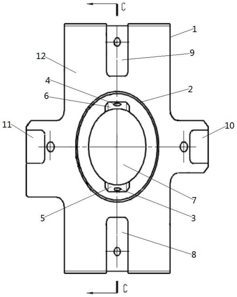
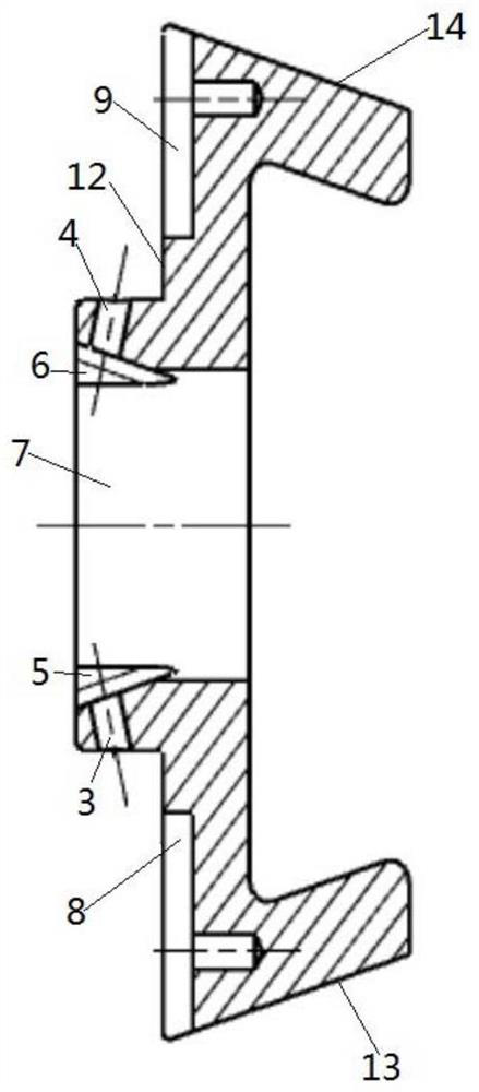
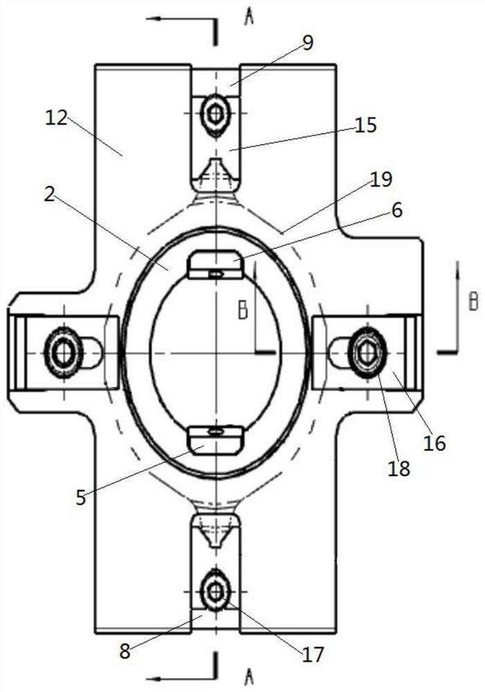
[0040] Such as figure 1 and figure 2 As shown, the present invention provides a positioning and clamping device for processing an inner oblique hole of a ring, including a positioning member 1, the surface of which a ring 19 is placed on the positioning member 1 is a processing surface 12, and the ring 19 and the positioning The contact surface of the part 1 is the placement surface 28, the processing surface 12 is provided with a cylinder 2 integrally formed with the positioning part 1, and the cylinder 2 on the processing surface 12 is used for clearance fit with the inner ring of the ring part 19 , wherein the diameter of the cylinder 2 is infinitely close to the diameter of the inner ring 27 of the ring member 19 and fits with a small gap, the end surface of the cylinder 2 is provided with a processing hole 7, and the processing hole 7 ru...


PUM


Abstract

The invention discloses a positioning and clamping device for machining an inclined hole in an annular part and a method of the positioning and clamping device for machining the inclined hole in the annular part. The positioning and clamping device comprises a positioning piece, a cylinder is integrally formed on the positioning piece, a first drill hole and a second drill hole are formed in the side face of the cylinder, the first drill hole is obliquely formed away from the machining face of the positioning piece, the inclination angle between the first drill hole and the machining face of the positioning piece is equal to the inclination angle between the first inclined hole in the annular part and the placing face, the first drill hole and the second drill hole are symmetrical with respect to the central axis of the cylinder, a first datum plane and a second datum plane are arranged on the side edge of the positioning piece, the first datum plane and the first drill hole complementeach other relative to the machining face of the positioning piece, the first datum plane and the second datum plane are symmetrical with respect to the central axis of the cylinder, and a fixing andclamping device is further arranged on the positioning piece and used for fixing the annular part. According to the positioning and clamping device, the annular part circumferential positioning is accurate, the indexing mode is simple, a drill bit is not prone to slipping, the structure is reasonable and simple, and the machining requirement of the annular part inclined hole is met.

Description

technical field [0001] The invention belongs to the field of mechanical processing, in particular to a positioning and clamping device and method for processing inclined holes inside ring parts. Background technique [0002] The nozzle is one of the parts of the engine. It is a ring. There are two bosses symmetrically arranged on the outer ring, and a ring groove is opened on the inner ring. Slanted holes are symmetrically arranged on the surface of the ring groove and the aforementioned inclined holes penetrate the bosses. Does not go through the boss, the plane where the center line of the inclined hole coincides with the plane where the center line of the boss is located, and the center line of the inclined hole is too close to the edge of the inner hole at the upper end of the nozzle, and this distance is smaller than the outer diameter of the machine drill chuck, so it can only be used Extended drill bit processing, the processing of this ring part adopts ordinary bench...

Claims


Application Information

Patent Timeline
IPC IPC(8): B23Q3/06B23B41/00
CPCB23B41/00B23Q3/062
Inventor 张小莉王涛李元秦瑾琦延梦莹杨柳川黄洪展冯建龙
Owner AECC AVIATION POWER CO LTD
Why Eureka
Try Eureka