
Shaft seal for a turbomachine

A shaft seal and seal technology, applied in the field of shaft seals, can solve the problems of high cost and high nitrogen consumption

Inactive Publication Date: 2012-02-08
SIEMENS AG
View PDF6 Cites 21 Cited by
  • Summary
  • Abstract
  • Description
  • Claims
  • Application Information

AI Technical Summary

Problems solved by technology

However, when turbocompressors are operated in petrochemical plants, the consumption of nitrogen as a blocking gas is so high that the outlay for supplying nitrogen and the costs associated therewith are considerably high

Method used


Image

  • Shaft seal for a turbomachine
  • Shaft seal for a turbomachine
  • Shaft seal for a turbomachine

Examples


Embodiment Construction

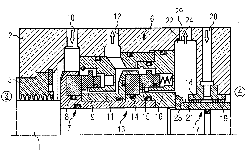
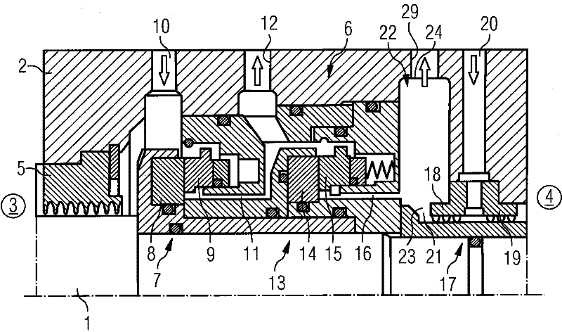
[0014] as from figure 1 and figure 2 As can be seen in the figure, the turbocompressor has a turbocompressor shaft 1 and a turbocompressor housing 2 , wherein the illustrated longitudinal end of the turbocompressor shaft 1 passes through the turbocompressor housing 2 .

[0015] The interior of the turbocompressor is formed by the process side 3 , whereas outside the turbocompressor there is an atmosphere 4 . On the process side, a higher than atmospheric pressure exists in the turbocompressor during operation, so that the turbocompressor shaft 1 can be sealed against the turbocompressor housing 2 from the process side 3 towards the atmosphere 4 . The sealing is achieved by means of a labyrinth seal 5 and a gas-lubricated slide ring seal 6, wherein the labyrinth seal 5 is arranged on the process side and the slide ring seal 6 is installed between the labyrinth seal 5 and the Atmosphere between 4. The gas-lubricated sliding ring seal 6 has a main seal 7 arranged directly dow...


PUM


Abstract

A shaft seal for a turbomachine, the process side (3) of which can be sealed off with respect to the atmosphere (4) by the shaft seal (7, 13, 17), has a process gas seal (7, 13), which can be acted on with a process gas (10) and blocked at the process side (3), and an atmosphere seal (17), which can be acted on with air (20) and blocked at the atmosphere side (4), and also a ventilation chamber (22) which runs around a shaft (1) of the turbomachine, which ventilation chamber (22) is arranged between the process gas seal (7, 13) and the atmosphere seal (17) in order to collect and discharge process gas leakage which has passed through the process gas seal (7, 13) and air leakage which has passed through the atmosphere seal (17), wherein the ventilation chamber (22) has, at the radially inner side thereof, a leakage inlet (23) and, at the radially outer side thereof, a leakage outlet (24), and also fittings (26, 27) between the leakage inlet (23) and the leakage outlet (24), wherein the fittings (26, 27) are dimensioned such that the ventilation chamber (22) has a flame barrier function with regard to an ignition of the leakage at the leakage inlet (23), and / or the leakage in the ventilation chamber (22) is not ignitable.

Description

technical field [0001] The invention relates to a shaft seal for a turbomachine. Background technique [0002] A turbomachine is understood to be, for example, a turbocompressor, an expander or a positive displacement compressor. A turbo compressor has a housing and a rotor mounted within the housing. The rotor has a shaft which is supported by its longitudinal end outside the housing. Thus, the longitudinal end of the shaft passes through the housing, wherein the shaft is sealed against the housing there by means of a shaft seal. Therefore, the inside of the turbo compressor is sealed from the atmosphere. The construction of the shaft seal is conventional such that, viewed from the inside of the turbocompressor, first the gas separation device and then the oil separation device are provided. The inner side of the turbocompressor, ie the process side, is separated from the atmosphere by means of a shaft seal and from the bearing area by means of an oil separator. The sh...

Claims


Application Information

Patent Timeline
Patent Type & Authority Applications(China)
IPC IPC(8): F16J15/34
CPCF16J15/40F16J15/3484
Inventor 卢德格尔·阿尔费斯沃尔夫冈·扎卡赖亚斯
Owner SIEMENS AG
Learn More