
Air outlet device of air conditioner indoor machine

A technology for indoor units and air outlet devices of air conditioners, which is applied in the direction of pipeline layout and airflow control components, can solve the problems of air conditioner space occupation, no driving device, and low assembly efficiency, so as to reduce failure rate, improve comfort, The effect of improving assembly efficiency

Active Publication Date: 2012-02-08
GD MIDEA AIR-CONDITIONING EQUIP CO LTD
View PDF7 Cites 16 Cited by
  • Summary
  • Abstract
  • Description
  • Claims
  • Application Information

AI Technical Summary

Problems solved by technology

[0003] Since the above-mentioned driving devices are separately installed in two different places, they need to occupy space separately. For thin-type air conditioners or air conditioners with two or more air outlets and need to control the air outlet swing separately, it is necessary There is not enough space to set up the drive unit
In addition, if the driving device for left and right swinging air is installed at the lower part of the air outlet of the air outlet frame, it is generally necessary to add a lower plate of the air outlet frame for fixing and installation. This structure will not only occupy the already narrow back pipe of the air conditioner. space, and the air guide vanes in the air outlet frame components are generally composed of two types of blades, the driving blade and the driven blade, in order to realize the automatic left and right swinging of the wind. They are very similar, so it takes a lot of time to distinguish the driving blade and the driven blade during the assembly process, so as not to install or wrongly install it, resulting in low assembly efficiency or product failure

Method used


Image

  • Air outlet device of air conditioner indoor machine
  • Air outlet device of air conditioner indoor machine
  • Air outlet device of air conditioner indoor machine

Examples


Embodiment Construction

[0033] The present invention will be further described below in conjunction with the accompanying drawings and embodiments.

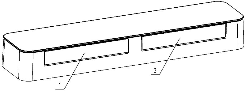
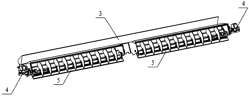
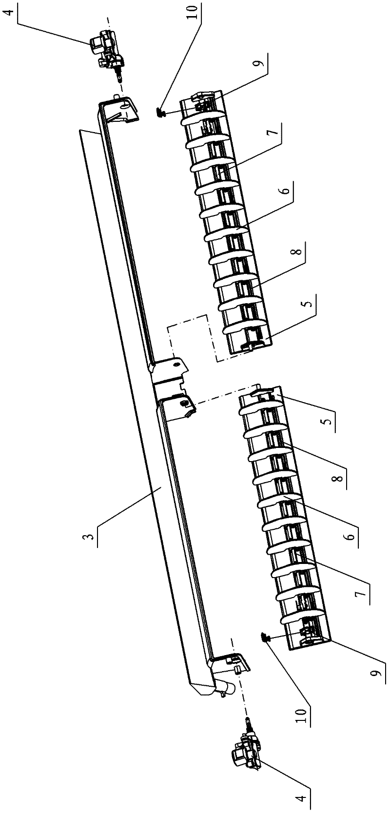
[0034] see Figure 1-Figure 13 , the air outlet device of the indoor unit of the air conditioner includes the first air outlet 1 and the second air outlet 2 arranged in the air outlet frame 3, and the first air outlet 1 and the second air outlet 2 are respectively provided with air deflectors 5 and wind guide vanes 6, the first air outlet 1 and the second air outlet 2 are respectively provided with a composite swing driving mechanism 4, the composite swing driving mechanism 4 includes a driving upper cover 13 and a driving lower cover 11 jointly surrounded by The first gear 12 and the transmission rack 15 are arranged in the chamber, the first gear 12 meshes with one end of the transmission rack 15, and the first gear 12 is connected with the output of the first driving motor 14 used for left and right swinging wind. The shafts are connected; the secon...


PUM


Abstract

The invention discloses an air outlet device of an air conditioner indoor machine, which comprises a first air outlet and a second air outlet that are arranged in an air outlet frame, wherein the first air outlet and the second air outlet are internally respectively provided with a wind deflector and a wind deflection blade, and also internally respectively provided with a compound swing drive mechanism, each compound swing wind drive mechanism comprises a chamber enclosed by a drive upper cover and a drive lower cover, the chamber is internally provided with a first gear and a transmission rack, the first gear is meshed with one end of the transmission rack, the first gear is connected with an output shaft of a first drive motor used as left and right swing wind, a second gear is sleeved on the middle of the transmission rack, a third gear is meshed with the second gear, and a flat shaft hole matched with an output shaft of a second drive motor used as up and down swing wind is arranged on a middle shaft of the third gear. The air outlet device has the characteristics of simple and reasonable structure, small volume, easiness in assembly, wider swing wind range and more selectable swing wind modes.

Description

technical field [0001] The invention relates to an air conditioner, in particular to an air outlet device of an indoor unit of the air conditioner. Background technique [0002] As people's requirements for living standards are getting higher and higher, many people will choose air conditioners with automatic up and down and left and right swing functions when buying air conditioners. The driving device of automatic wind swing. And the driving device of the air conditioner with this up and down and left and right automatic swinging functions in the market is generally separated separately and arranged at two different positions in the air conditioner. Specifically, there are the following situations: 1) respectively set on both sides of the air outlet frame at the air outlet; 2) the drive device for swinging the wind up and down is set It is arranged at the lower part of the air outlet of the air outlet frame. [0003] Since the above-mentioned driving devices are separat...

Claims


Application Information

Patent Timeline
Patent Type & Authority Applications(China)
IPC IPC(8): F24F13/06F24F13/14
Inventor 苏炳超叶月华苗永福万兴云
Owner GD MIDEA AIR-CONDITIONING EQUIP CO LTD
Learn More