
Controller for fuel injection

A fuel injector and fuel injection technology, applied in the directions of fuel injection control, electrical control, engine control, etc., can solve the problem of not being able to control the end time of fuel injection with high accuracy.

Inactive Publication Date: 2014-05-28
DENSO CORP
View PDF6 Cites 0 Cited by
  • Summary
  • Abstract
  • Description
  • Claims
  • Application Information

AI Technical Summary

Problems solved by technology

If the learning values ​​G1-G5 in the learning areas A1-A5 are linearly interpolated as shown by the dotted lines, the energization period may be determined based on an incorrect relationship deviating from the actual relationship, and thus cannot be controlled with high accuracy fuel injection end time

Method used


Image

  • Controller for fuel injection
  • Controller for fuel injection
  • Controller for fuel injection

Examples


Embodiment Construction

[0022] Hereinafter, an embodiment of the fuel injection state detector according to the present invention will be described. The fuel injection state detector is applied to an internal combustion engine (diesel engine) having four cylinders #1-#4.

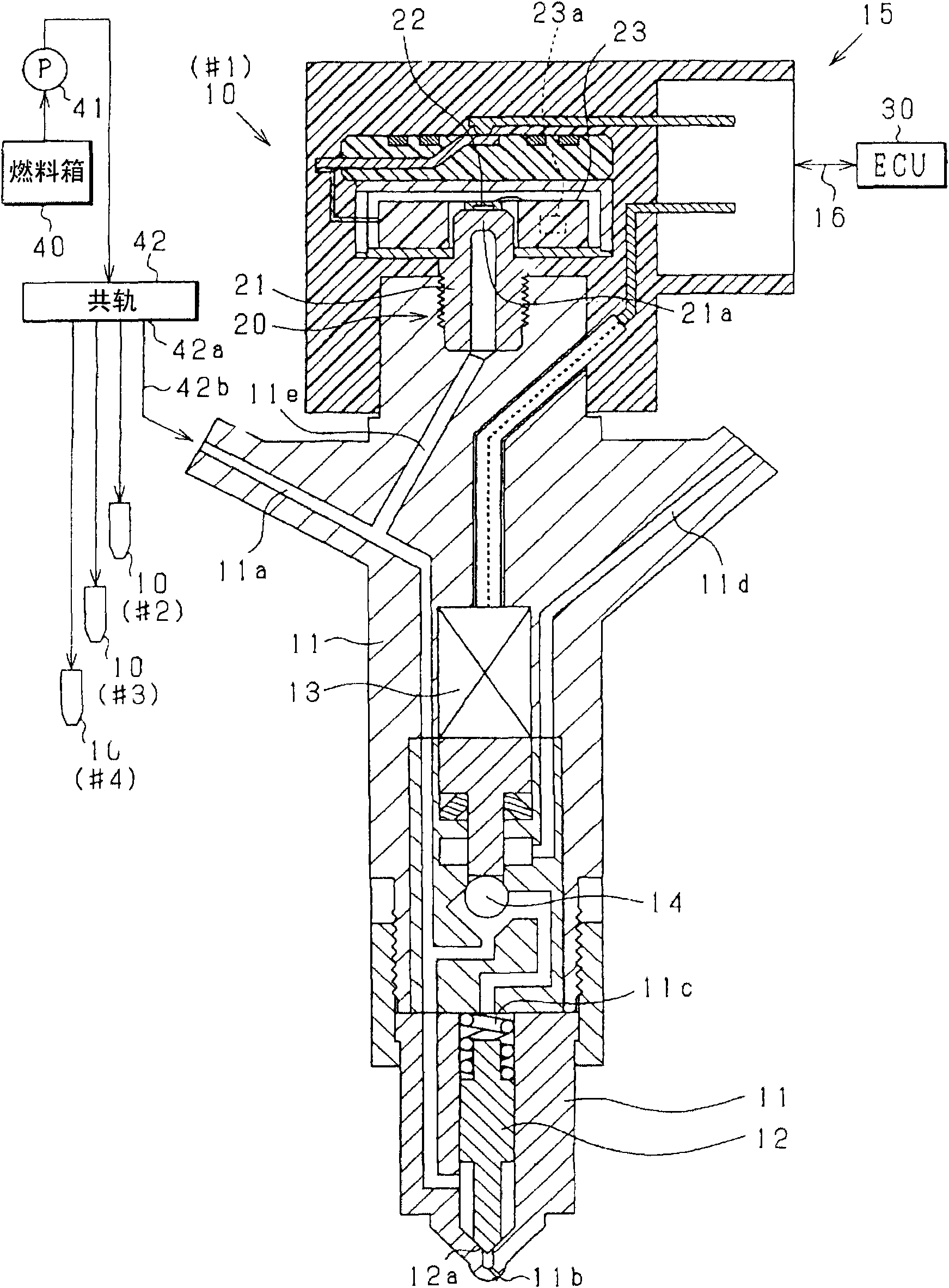
[0023] figure 1 is a schematic diagram showing a fuel injector 10 provided to each cylinder, a fuel pressure sensor 20 provided to each fuel injector, an electronic control unit (ECU) 30 , and the like.

[0024] First, the fuel injection system of the engine including the fuel injector 10 will be explained. The fuel in the fuel tank 40 is pumped by the high-pressure pump 41 and accumulated in the common rail 42 to be supplied to each fuel injector 10 (#1-#4). The fuel injectors 10 (#1-#4) sequentially perform fuel injection in a predetermined order. The high-pressure pump 41 is a piston pump that discharges high-pressure fuel intermittently.

[0025] The fuel injector 10 is composed of a main body 11, a needle valve main body ...


PUM


Abstract

Provided is a controller for fuel injection, comprising a parameter obtaining part (33a) for obtaining the parameter (R4) of the injection velocity waveform indicating the changes of the injection velocity based on the detecting value of the fuel pressure sensor, a learning part (33b) used for learning the fuel injection order signal (Tq) of the fuel injector and the parameter (R4) corresponding to the fuel injection order signal as the learning value, a storage part (32) used for storing and indicating the model waveform (M3) of the parameter (R4) changes resulting from the changes of the fuel injection order signal (Tq), and an inner inserting part (33c) used for inserting the learning value and calculating the fuel injection order signal (Tq) and the parameters (R4) of the fuel injection order signal by utilizing the model waveform (M3).

Description

technical field [0001] The present invention relates to a fuel injection controller that controls a fuel injection state based on a pressure waveform indicative of a change in fuel pressure. This change in fuel pressure is caused by fuel injection through the fuel injector and is detected by a fuel pressure sensor. Background technique [0002] It is important to detect fuel injection states such as fuel injection start timing, fuel injection amount, etc. to precisely control output torque and emissions of an internal combustion engine. [0003] JP-2010-3004A and JP-2009-57924A describe that a fuel pressure sensor detects a change in fuel pressure in a fuel supply passage due to fuel injection. The fuel supply passage extends from the common rail to injection ports of the fuel injectors. Since the pressure waveform detected by the fuel pressure sensor is highly correlated with the injection rate waveform indicating a change in the fuel injection rate, it is possible to det...

Claims


Application Information

Patent Timeline
Patent Type & Authority Patents(China)
IPC IPC(8): F02D41/38
CPCF02D41/247F02D41/2416F02D2200/0602F02D2250/04F02D41/2467
Inventor 小松航
Owner DENSO CORP
Learn More