
Automatic fly larva pupating separation device

An automatic separation and pupation technology, which is applied in animal husbandry and other fields, can solve the problems of reducing the emergence rate of fly pupae, drowning, and reducing work efficiency, so as to avoid drowning, improve efficiency, and prevent flight.

Inactive Publication Date: 2012-02-08
哈尔滨市疾病预防控制中心
View PDF7 Cites 4 Cited by
  • Summary
  • Abstract
  • Description
  • Claims
  • Application Information

AI Technical Summary

Problems solved by technology

[0003] The present invention solves the problem that in the current process of raising fly maggots in the laboratory, after the fly maggots pupate, the feed is separated from the fly pupae by washing the pupae, resulting in a decrease in work efficiency, and some fly pupae are drowned in water, which reduces the eclosion rate of fly pupae. problem, and then propose an automatic separation device for fly maggot pupation

Method used


Image

  • Automatic fly larva pupating separation device
  • Automatic fly larva pupating separation device
  • Automatic fly larva pupating separation device

Examples


specific Embodiment approach 1

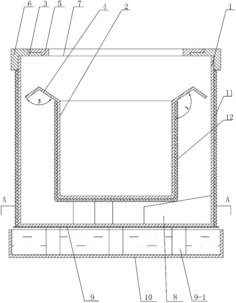
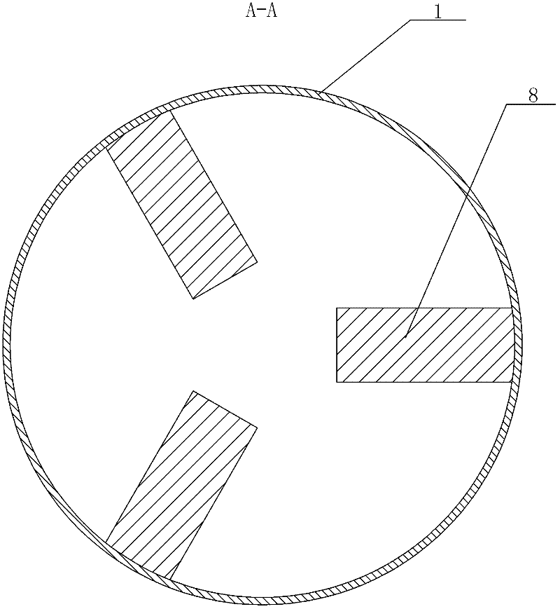
[0007] Specific implementation mode one: combine Figure 1 to Figure 5 To illustrate this embodiment, a fly maggot pupation automatic separation device described in this embodiment includes an outer cylinder 1, an inner cylinder 2 and a cylinder head assembly 3, and the opening edge of the inner cylinder 2 is provided with an inverted V-shaped Edge 4, the inner cylinder 2 is placed in the outer cylinder 1, and the cylinder head assembly 3 is buckled at the opening of the outer cylinder 1.

specific Embodiment approach 2

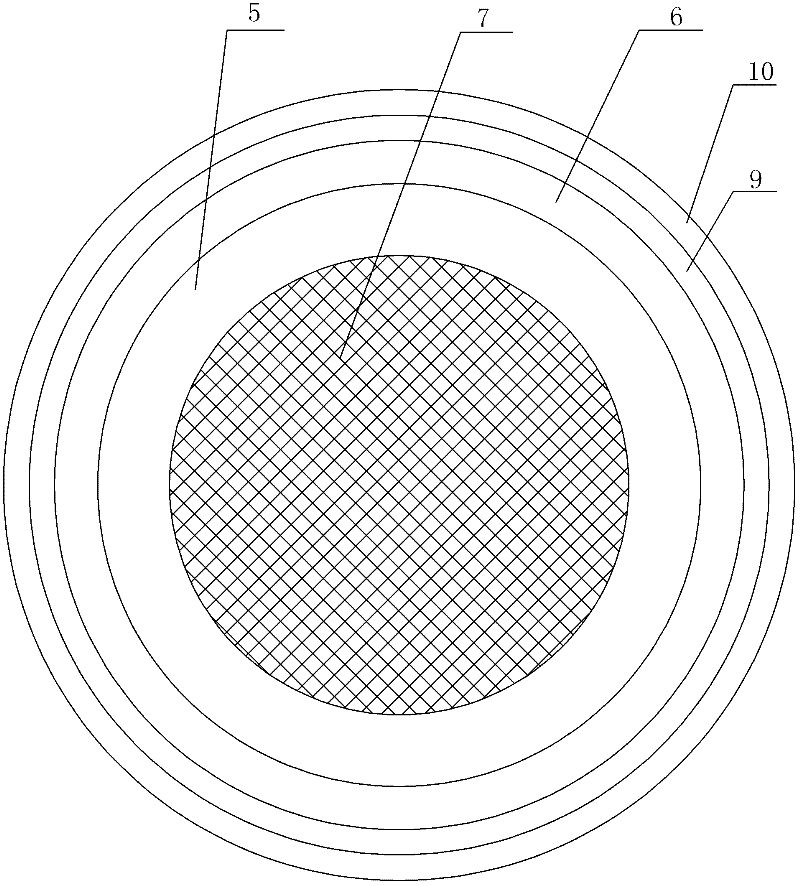
[0008] Specific implementation mode two: combination figure 1 , Figure 4 with Figure 5 Describe this embodiment, the cylinder head assembly 3 of a kind of fly maggot pupation automatic separation device described in this embodiment includes an upper cover 5, a lower cover 6 and a nylon net 7, and the middle part of the lower cover 6 has a first through hole 6-1, the hole wall of the first through hole 6-1 is provided with an annular flange 6-2, and the upper cover 5 and the nylon mesh 7 are sequentially installed on the annular flange 6-2 from top to bottom, A second through hole 5-1 is opened in the middle of the upper cover 5, and the centerline of the second through hole 5-1 coincides with the centerline of the first through hole 6-1. This embodiment prevents fly larvae from fleeing during the growth process, and the nylon mesh 7 ensures the smooth flow of air in the outer cylinder 1 and the inner cylinder 2. Other components and connections are the same as those in th...

specific Embodiment approach 3

[0009] Specific implementation mode three: combination figure 1 Describe this embodiment, the included angle β of the opening of the inverted V-shaped edge 4 of the automatic separation device for fly maggot pupation described in this embodiment is 105°, and the side where the inverted V-shaped edge 4 is connected to the opening edge of the inner cylinder 2 The angle γ with the outer wall of the inner cylinder 2 is 120°. Other components and connections are the same as those in the first embodiment.


PUM


Abstract

The invention relates to a separation device, in particular to an automatic fly larva pupating separation device. The problems of reducing the working efficiency, drowning a part of fly larvae in water and reducing the fly pupa emergence rate by separating feed from fly larvae in a pupa washing manner after pupating fly larvae in the current fly larva feeding process in a laboratory are solved. The device disclosed by the invention comprises an outer cylinder and further comprises an inner cylinder and a cylinder cover assembly. An outward extension converse V-shaped edge is arranged at the opening edge of the inner cylinder. The inner cylinder is arranged in the outer cylinder. The cylinder cover assembly is arranged at the opening of the outer cylinder in a buckling manner. The device disclosed by the invention is used for feeding fly larvae in the laboratory and automatically separating fly larvae from feed.

Description

Technical field [0001] The invention relates to a separation device, in particular to an automatic separation device for fly larvae pupating. Background technique [0002] Maggots, that is, fly larvae, feed on livestock and poultry manure, wheat bran, various rotten platycodon, vegetable leaves, bean cakes and other organic matter, and grow and reproduce very quickly. Maggot protein is a high-quality protein that is not only high-quality feed, but can also be used to extract protein powder, develop advanced nutritional products, aerospace food, medicine, etc. Currently, the method of raising fly larvae in the laboratory is to mix fly larvae and feed into a breeding tank. After the fly larvae pupate, the feed and fly pupae are separated. However, it is difficult to separate the fly pupae and feed after the fly larvae pupate. Traditional methods The separation method is to wash the pupae, that is, put the fly pupae and the feed into the water, and separate the fly pupae and t...

Claims


Application Information

Patent Timeline
Patent Type & Authority Applications(China)
IPC IPC(8): A01K67/033
Inventor 王玥刘岩琳姜博周浩孙宗祥杨一偲姜永波王文峰任力曲雯张雅明张文佳王健高晓丽王永革蔡路罗超唐道洲王文琳
Owner 哈尔滨市疾病预防控制中心
Learn More