Rotary oil draining device

A technology of inner pipe and track, which is applied in the field of rotary oil drainer, can solve problems such as accidents caused, slips cannot be opened radially, and oil drainer is opened to drain oil, etc., to achieve reliable operation, high operation success rate, and wide application range big effect

Inactive Publication Date: 2012-02-01
CHINA PETROLEUM & CHEM CORP +1
View PDF7 Cites 4 Cited by
  • Summary
  • Abstract
  • Description
  • Claims
  • Application Information

AI Technical Summary

Problems solved by technology

The operator’s misoperation is due to the need to lift the oil pipe in the process of lowering the oil pipe and the hard-to-change habit formed over the years, which may cause the oil drain to be opened and drained.
Chinese patent application 00258996.6 "slip type rotary oil drainer", the slips cannot be radially opened and cannot be stuck on the casing, so no oil is drained, even if the slips can be radially opened and stuck on the casing, the leakage After oiling, the slips sometimes cannot be retracted and the pipe string is stuck, causing accidents
Another example is the Chinese patent application 2007200290118 "A Rotary Oil Drainer", which has a simple structure, but its sealing sleeve (5) and the inner pipe (3) are threaded. Because some wells have problems such as scaling and corrosion, It is easy to cause the connecting thread between the sealing sleeve (5) and the inner pipe (3) to be unable to be loosened and the oil cannot be drained

Method used


Image

  • Rotary oil draining device
  • Rotary oil draining device
  • Rotary oil draining device

Examples


Embodiment Construction

[0009] Embodiments of the present invention will be described below in conjunction with the accompanying drawings.

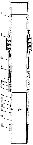
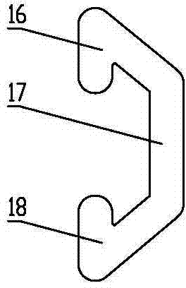
[0010] Embodiments of the present invention include an upper joint 1, a friction mechanism 2, a connecting sleeve 3, a track pin 4, a locking sleeve 5, a locking ball 8, a sealing sleeve 9, an upper sealing ring 11, a lower sealing ring 13, an inner pipe 14, and an upper joint 1 is connected to the upper part of the inner tube 14, there is a track 7 on the inner tube 14, the front end of the track pin 4 is inserted into the track on the inner tube 14, there is a lock ball groove on the inner tube 14, the oil drain hole 12 on the inner tube 14, the sealing sleeve 9 is set on the inner tube 14, the sealing sleeve 9 covers the oil drain hole 12, the upper sealing ring 11 and the lower sealing ring 13 are installed between the inner tube 14 and the sealing sleeve 9, the upper sealing ring 11 is on the oil drain hole 12, The lower sealing ring 13 is under the oil dra...


PUM


Abstract

The invention relates to a rotary draining device. In the rotary draining device, an inner pipe is provided with a track; the front end of a track pin is inserted into the track on the inner pipe; a sealing sleeve is sleeved on the inner pipe; the sealing sleeve covers an oil draining hole; an upper sealing ring and a lower sealing ring are arranged between the inner pipe and the sealing sleeve; the sealing sleeve is hung on the inner pipe through a lock ball; the lower part of a lock sleeve covers the lock ball; a releasing slot is formed in the lock sleeve; the lower part of a friction mechanism is connected with the upper part of a connecting sleeve; the lower part of the connecting sleeve is connected with the lock sleeve; the connecting sleeve covers the track pin; the sealing sleeve is provided with a through hole; and the track pin can move from an upper track slot to a lower track slot. When the rotary oil draining device drains oil, an oil pipe is laid down, rotated and lifted to drain oil; the time when the oil is drained can be manually controlled voluntarily, tools and sucker rods for starting the oil draining device are not required to be invested, and the rotary oil draining device is not influenced by the separation of the sucker rods; the drift diameter of the inner pipe is same as that of the oil pipe on a pump, and various matched tools can be laid down, so that the rotary oil draining device has a wide application range, can be repeatedly operated, and works reliably and is high in an operation success rate.

Description

technical field [0001] The invention relates to a downhole tool for oil recovery in an oil field, in particular to an oil drainer, in particular to a rotary oil drainer. Background technique [0002] There are many kinds of existing oil drainers, such as Chinese patent application 96238554.9 "a split-type lifting and rotating oil drainer", its support type unlocking assembly will be in contact with the oil draining assembly to drain oil when the oil pipe is lifted up, When the operator makes an operation error or runs into a new situation in the process of going down the well and needs to lift the oil pipe, the oil drain will be opened to drain the oil, making the operation unsuccessful. Another example is Chinese patent application 00247456.5 "lifting rotary oil drainer", also there is the problem of above-mentioned patent. The operator's misoperation is because the operation of lifting the oil pipe itself and the hard-to-change habit developed for many years in the proces...

Claims


Application Information

Patent Timeline
Patent Type & Authority Applications(China)
IPC IPC(8): E21B34/12
Inventor 王天正张峻李洪强邵宣涛郑党明乔卫平孙继志孙磊高峰罗惜强
Owner CHINA PETROLEUM & CHEM CORP
Why Eureka
Try Eureka