
Hydraulic control system of crane and winch device of crane

A technology of hydraulic control system and hoisting device, applied in the direction of hoisting device, spring mechanism, etc., can solve the problems of complex structure, miscalculation and high price of pressure memory valve

Inactive Publication Date: 2012-02-01
XUZHOU HEAVY MASCH CO LTD
View PDF5 Cites 27 Cited by
  • Summary
  • Abstract
  • Description
  • Claims
  • Application Information

AI Technical Summary

Problems solved by technology

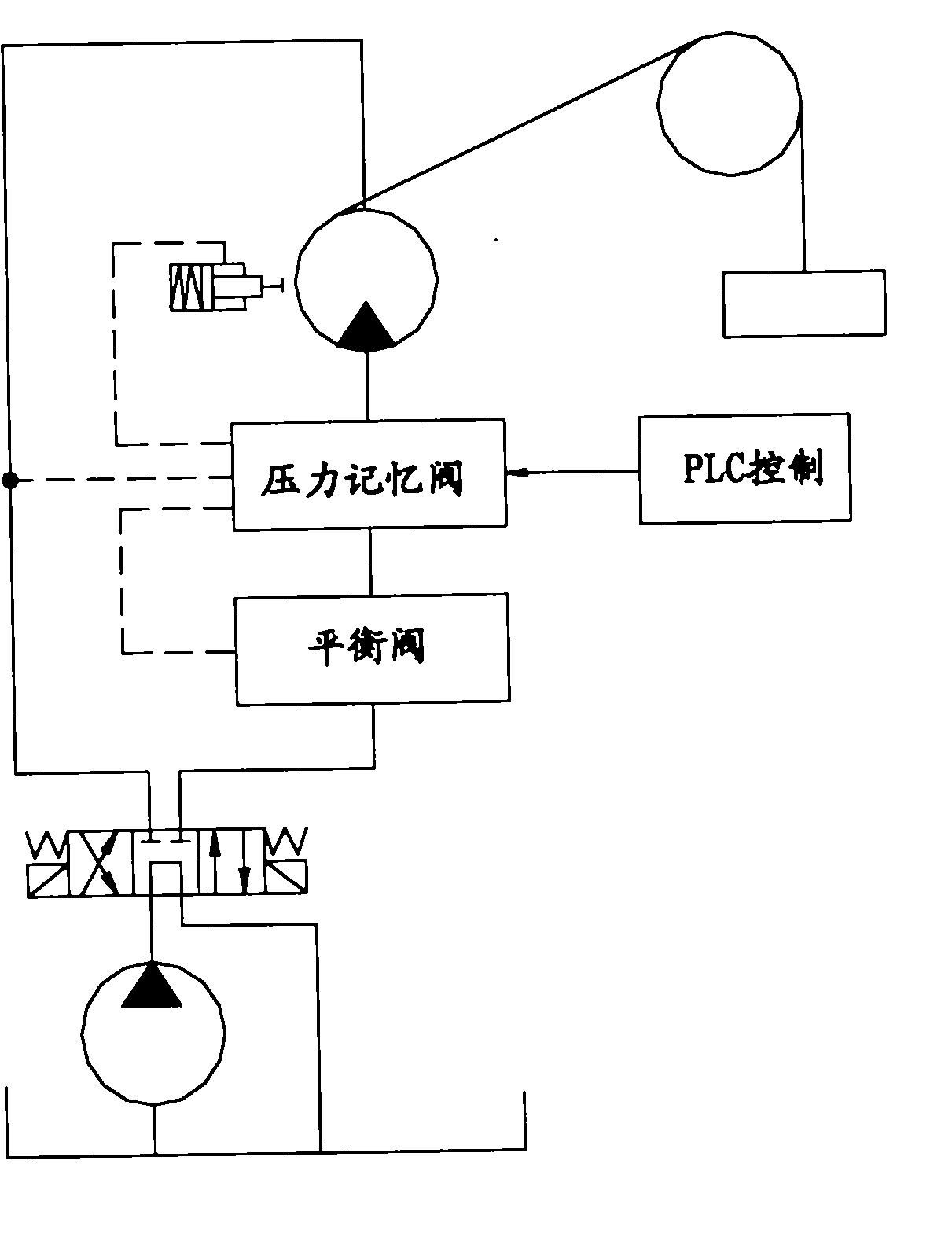
[0006] (1) Electrically controlled pressure memory valve has complex structure, high price and high cost;
[0007] (2) When a pressure shock occurs in the system, the pressure relay will record the shock value, resulting in miscalculation

Method used


Image

  • Hydraulic control system of crane and winch device of crane
  • Hydraulic control system of crane and winch device of crane
  • Hydraulic control system of crane and winch device of crane

Examples


Embodiment Construction

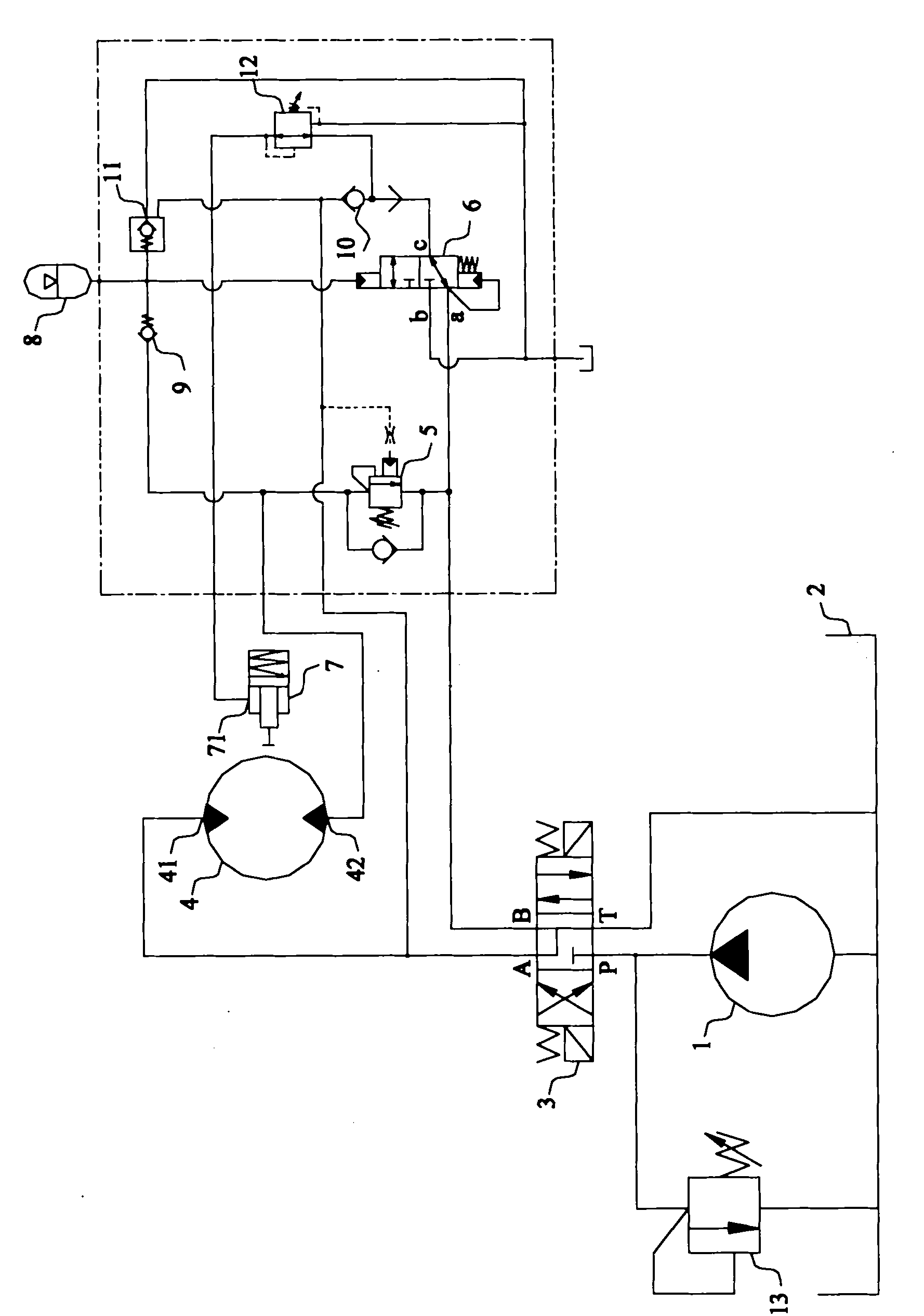
[0027] The core of the present invention is to provide a hydraulic control system for the hoisting device. From the perspective of stabilizing the opening pressure of the brake, the working pressure of the system is memorized through the hydraulic pressure memory device; the system is improved on the basis of effectively reducing the manufacturing cost. Reliability of work.

[0028] Hereinafter, this embodiment will be described in detail with reference to the drawings in the specification.

[0029] See figure 1 This figure is a schematic diagram of the overall structure of the crane in this embodiment.

[0030] It should be noted that the main functional components of the crane, such as the traveling system, power system, boom system, hoisting system, and electrical system, are completely the same as the prior art. Those skilled in the art do not need to pay creative labor based on the prior art. It can be achieved, so I won't repeat it here.

[0031] The hoist of the crane is drive...


PUM


Abstract

The invention discloses a hydraulic control system of a winch system. The hydraulic control system comprises a motor for a driving roller and an oil cylinder of a brake roller. The hydraulic control system further comprises a hydraulically operated direction control valve with two work positions and an energy accumulator, wherein the hydraulically operated direction control valve is arranged between an oil port of the direction control valve, which is communicated with a winch rope folding and liquid feeding port of the motor and a brake removing liquid inlet of the oil cylinder; at the first work position, the oil port of the direction control valve, which is communicated with the winch rope folding and liquid feeding port of the motor, is conducted with an oil return path; the winch rope folding and liquid feeding port of the motor is unidirectionally conducted with an oil port of the energy accumulator; the winch rope folding and liquid feeding port of the motor in the direction control valve is communicated with a chamber where one end of a valve core is arranged and is used for pushing the valve core to generate the trend of sliding towards the first work position; and the oil port of the energy accumulator is communicated with a chamber where the other end of the valve core is arranged and is used for pushing the valve core to generate the trend of sliding towards the second position. The invention further provides a crane adopting the hydraulic control system.

Description

Technical field [0001] The invention relates to the technical field of engineering machinery, in particular to a hydraulic control system of a crane and its hoisting device. Background technique [0002] During the normal operation of the crane, lifting and lowering heavy objects by the cooperation of the hoisting motor and the brake cylinder is one of the main functions of the crane. Specifically, when the hoist is in a non-working state, the oil-controlled hoist brake is normally closed; when the hoist lifts heavy objects, the hydraulic system usually supplies oil to the hydraulic motor and the hoist brake cylinder at the same time to release the hoist brake , So that the winch can rotate without obstacles. [0003] In the actual hoisting process, many working conditions often require heavy objects to stay at a certain height for a period of time, and then continue to lift; that is, the second lifting operation. In the prior art, the staying and keeping of heavy objects in the ...

Claims


Application Information

Patent Timeline
Patent Type & Authority Applications(China)
IPC IPC(8): B66D1/08B66D1/44
Inventor 刘邦才冯文昌王清送胡小冬
Owner XUZHOU HEAVY MASCH CO LTD
Learn More