Rotary installation machine of movable optical-fiber connector
A movable connector and transmission connection technology, which is applied in the direction of hand-held tools and manufacturing tools, can solve the problems of insufficient screwing and low efficiency of manual assembly, so as to improve assembly efficiency, increase the pass rate of one-time assembly, and reduce production costs. The effect of cost of use
- Summary
- Abstract
- Description
- Claims
- Application Information
AI Technical Summary
Problems solved by technology
Method used
Image
Examples
Embodiment 1
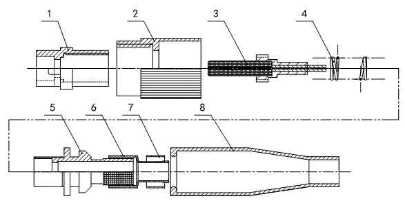
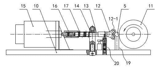
[0022] Embodiment 1: The specific embodiment of the optical fiber movable connector spinning machine of the present invention is as follows Figure 3 to Figure 7 As shown, the spinning machine has a base 10, a set of motor drive mechanism 21 is fixedly installed on the installation platform at the top of the base 10, the power output shaft of the motor drive mechanism 21 is horizontally arranged, and radially fixed on the power output shaft A driving wheel 11 utilizing frictional force to drive the parts to be installed, the driving wheel 11 is made of rubber wheels, and a pressure head 12 is provided near the outer rim of the driving wheel 11 left side, on the pressure head 12 towards the The front end of the driving wheel 11 is rotated up and down side by side with two pressure rollers 12-1. The axis of these two pressure rollers 12-1 is parallel to the axis of the driving wheel 11, so that the pressure head 12 is aligned with the outer rim of the driving wheel 11. A three-p...
Embodiment 2
[0026] Embodiment two: if Figure 8 As shown, the difference between the second embodiment and the first embodiment lies in the torque control device. Specifically, the installation rod 18 used for positioning the sleeve 1 before anti-rotation assembly is a split structure. The sleeve 1 is composed of the installation part 18-5, wherein a connection hole is opened on the front end surface of the handle part 18-4, and an insertion hole that is inserted and rotated with the connection hole is protruded on the rear end of the installation part 18-5. Follow up. The torque control device is composed of a damping layer 18-5 that prevents rotation between the handle portion 18-4 and the mounting portion 18-5, which is placed between the outer peripheral surface of the plug-in section and the inner hole wall of the connecting hole.
[0027] When in use, the staff holds the hand-held part 18-4 at the rear end of the installation rod 18, and the hand-held part 18-4 utilizes the dampin...
PUM
 Abstract
Description
Claims
Application Information
 - Generate Ideas
- Intellectual Property
- Life Sciences
- Materials
- Tech Scout
- Unparalleled Data Quality
- Higher Quality Content
- 60% Fewer Hallucinations
Browse by: Latest US Patents, China's latest patents, Technical Efficacy Thesaurus, Application Domain, Technology Topic, Popular Technical Reports.
© 2025 PatSnap. All rights reserved.Legal|Privacy policy|Modern Slavery Act Transparency Statement|Sitemap|About US| Contact US: help@patsnap.com


