
Mid-infrared fiber laser

A laser, infrared light technology, applied in the laser field, can solve the problems of low oscillation efficiency, complex, unsuitable for field or airborne use, etc., and achieve the effect of improving conversion efficiency and output power

Inactive Publication Date: 2012-01-25
SHENZHEN DAWEI PHOTOELECTRIC TECH
View PDF3 Cites 8 Cited by
  • Summary
  • Abstract
  • Description
  • Claims
  • Application Information

AI Technical Summary

Problems solved by technology

[0002] Mid-infrared lasers are widely used in national defense (jamming / blinding infrared guidance and thermal imaging cameras), biochemical (gas molecule detection), medical (bone / dental applications, surgery, pathological examination) and semiconductor technology (monitoring of plasma etching) It has important applications, but due to the lack of high-efficiency gain media in the mid-infrared band, the main means of generating lasers are parametric oscillation and frequency doubling
However, there are different problems in several existing lasers: semiconductor lasers of indium arsenic antimony and lead salts have extremely low efficiency and can only produce microwatt-level output; parametric oscillation schemes of solid-state lasers are difficult to achieve high average output power due to heat dissipation problems; carbon dioxide The frequency doubling efficiency of the laser is high, but it is not suitable for field or airborne use; the existing fiber laser parametric oscillation scheme requires a complex, expensive narrow spectral width, linearly polarized main laser oscillation power amplification (MOPA) fiber laser, and the parametric oscillation efficiency outside the cavity Low
Generally speaking, none of the existing mid-infrared lasers can obtain high-power stable mid-infrared laser

Method used


Image

  • Mid-infrared fiber laser
  • Mid-infrared fiber laser

Examples


Embodiment Construction

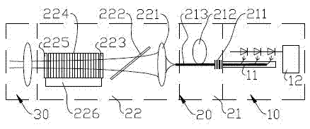
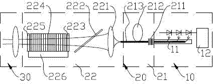
[0019] The present invention will be further described below in combination with specific embodiments. Such as figure 1 Shown is an embodiment of the mid-infrared fiber laser of the present invention, including a pre-pumping system 10 , a resonant cavity 20 and an output system 30 . The resonant cavity 20 is composed of a gain system 21 and an optical parametric oscillation system 22 . The gain system 21 includes a fiber grating 211 , a gain fiber 212 and a passive fiber 213 connected to each other, and the fiber grating 211 is connected to the pumping system 10 through an optical fiber. The optical parametric oscillation system 22 includes a focusing lens group 221, a Brewster polarizer 222, a nonlinear optical crystal 224, a short-pass filter 223 arranged in front of the nonlinear optical crystal 224, and a short-pass filter 223 arranged in front of the nonlinear optical crystal 224. Long pass filter 225. The light beam output from the passive optical fiber 213 enters the...


PUM

PropertyMeasurementUnit
Wavelengthaaaaaaaaaa

Abstract

The invention relates to the technical field of laser, and in particular relates to a mid-infrared fiber laser. The laser comprises a preposed pumping system, a resonant cavity and an output system. The laser is characterized in that the resonant cavity comprises a gain system and an optical parametric oscillator system; the gain system comprises a fiber Bragg grating, a gain fiber and a passive fiber, which are connected with one another; the fiber Bragg grating is connected with the pumping system by fibers; the optical parametric oscillator system comprises a focusing lens group, a Brewster polaroid, a nonlinear optical crystal, a short wave pass filter and a long wave pass filter, which are arranged in sequence; the short wave pass filter is arranged in front of the nonlinear optical crystal; the long wave pass filter is arranged behind the nonlinear optical crystal; and the light beams output by the passive fiber enter into the optical parametric oscillator system through the focusing lens group, enter into the output system through the long wave pass filter and are output after being shaped. The mid-infrared fiber laser has the following beneficial effects: the output power of a mid-infrared laser is improved; and the mid-infrared fiber laser is firm and durable.

Description

technical field [0001] The invention relates to the field of laser technology, in particular to a mid-infrared fiber laser. Background technique [0002] Mid-infrared lasers are widely used in national defense (jamming / blinding infrared guidance and thermal imaging cameras), biochemical (gas molecule detection), medical (bone / dental applications, surgery, pathological examination) and semiconductor technology (monitoring of plasma etching) It has important applications, but due to the lack of high-efficiency gain media in the mid-infrared band, the main means of generating lasers are parametric oscillation and frequency doubling. However, there are different problems in several existing lasers: semiconductor lasers of indium arsenic antimony and lead salts have extremely low efficiency and can only produce microwatt-level output; parametric oscillation schemes of solid-state lasers are difficult to achieve high average output power due to heat dissipation problems; carbon di...

Claims


Application Information

Patent Timeline
IPC IPC(8): H01S3/067H01S3/10
Inventor 苏秉华蔡波薛竣文
Owner SHENZHEN DAWEI PHOTOELECTRIC TECH
Learn More