Structure of a build-in screw in a bushing and corresponding sensor housing

A sensor housing and screw technology, applied in the direction of screws, nuts, connecting components, etc., to achieve the effect of easy use and manufacture

Active Publication Date: 2012-01-25
ROBERT BOSCH GMBH
View PDF9 Cites 0 Cited by
  • Summary
  • Abstract
  • Description
  • Claims
  • Application Information

AI Technical Summary

Problems solved by technology

Here, the screw can only be assembled during the press-in process, but additional parts are required

Method used


Image

  • Structure of a build-in screw in a bushing and corresponding sensor housing
  • Structure of a build-in screw in a bushing and corresponding sensor housing
  • Structure of a build-in screw in a bushing and corresponding sensor housing

Examples


Embodiment Construction

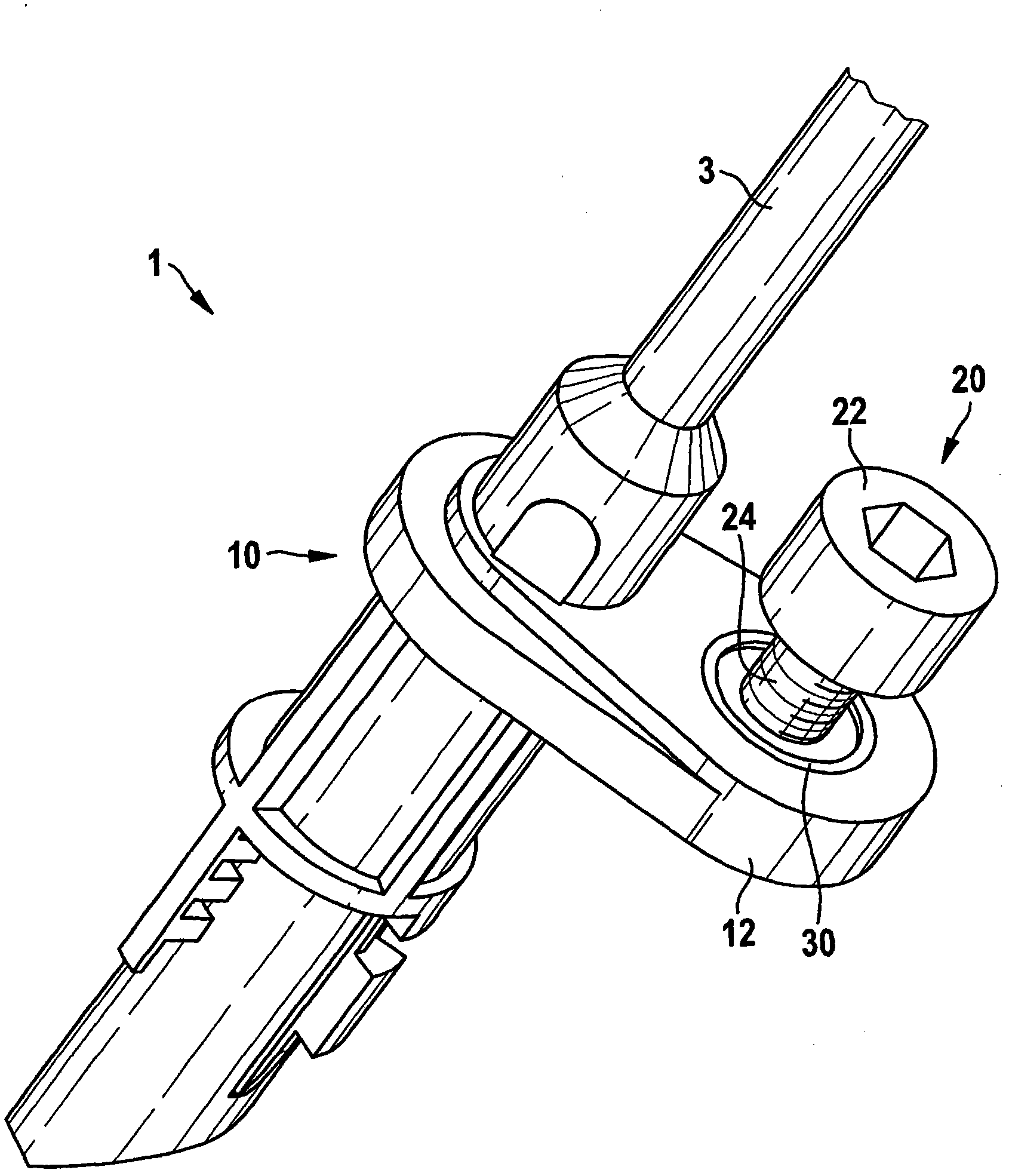
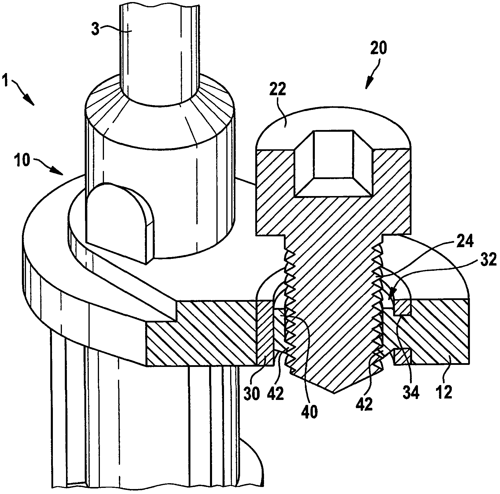
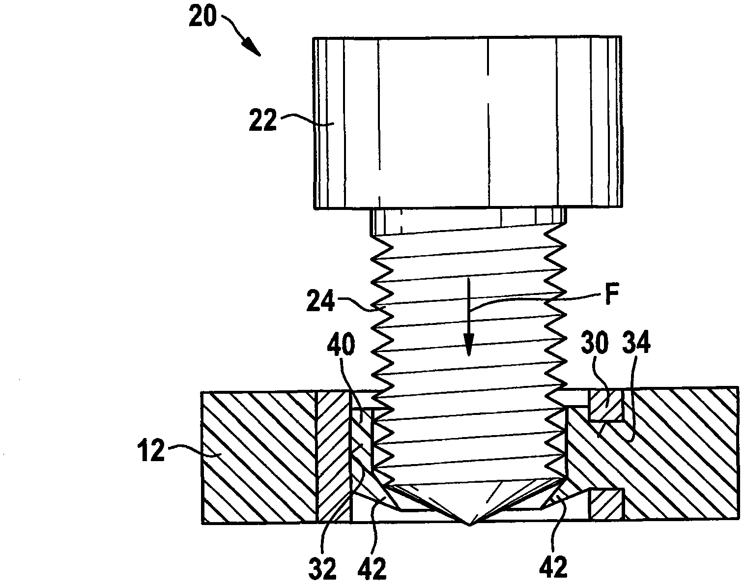
[0016] refer to Figures 1 to 4 , the illustrated embodiment of the invention utilizes the construction of a built-in screw 20 in a bushing 40 . The screw includes a head 22 and a threaded shank 24 . The screw head 22 is designed and arranged to turn the screw 20 , the screw head 22 here comprising, for example, a hexagonal recess for this purpose. The bushing 30 is fixedly connected to the fastening attachment 12 of the sensor housing 10 of the sensor unit 1 . In addition, the sensor unit 1 includes a connection cable 3 for electrically connecting a sensor element (not shown) inside the sensor housing 10 . Preferably, the sensor housing 10 is an injection-molded part, wherein the metal bushing 30 is used as an insert in a corresponding injection-molding process.

[0017] According to the invention, the bushing 30 is made of metal and comprises a portion 40 of elastic material at the inner region 32 in which the threaded shank 24 of the screw 20 deforms the flexible region ...


PUM


Abstract

An improved structure of a build-in screw (20) in a bushing (30) comprises a bushing (30) made of metal and an elastic material (40) at an inner region (32) forming a flexible area (42) in which a thread shank (24) of said screw (20) is pressed in by deforming said flexible area (42), so that said screw (20) and said metal bushing (30) are captively connected.

Description

technical field [0001] The present invention relates generally to the field of mounts and / or fasteners for sensor units in vehicles, and in particular to the construction of built-in screws in bushings and to corresponding sensor housings. Background technique [0002] Known arrangements of built-in screws in bushings require the screw to be rotated for the fixing process. Therefore, the screw is fixed by self-tapping at the plastic part inside the bushing. Another known construction of a built-in screw in a bushing is to use an extra part to fix the screw. Here, the screws can only be assembled during the press-in process, but additional parts are required. [0003] In patent application publication DE 197 45 894 A1 a screw connection for an airbag housing is described. The screw connection for the airbag housing comprises a threaded hole formed in a cylindrical bushing in the wall of the support structure or in the airbag housing by plastic flow forming middle. With t...

Claims


Application Information

Patent Timeline
IPC IPC(8): F16B29/00
CPCF16B37/0842
Inventor 二宫健一
Owner ROBERT BOSCH GMBH
Why Eureka
Try Eureka