Welding inspection method and apparatus thereof
A technology for welding inspection and equipment, which is applied in welding equipment, metal processing equipment, processing detection response signals, etc., and can solve problems such as failure to provide reference signals
- Summary
- Abstract
- Description
- Claims
- Application Information
AI Technical Summary
Problems solved by technology
Method used
Image

Examples
no. 1 example
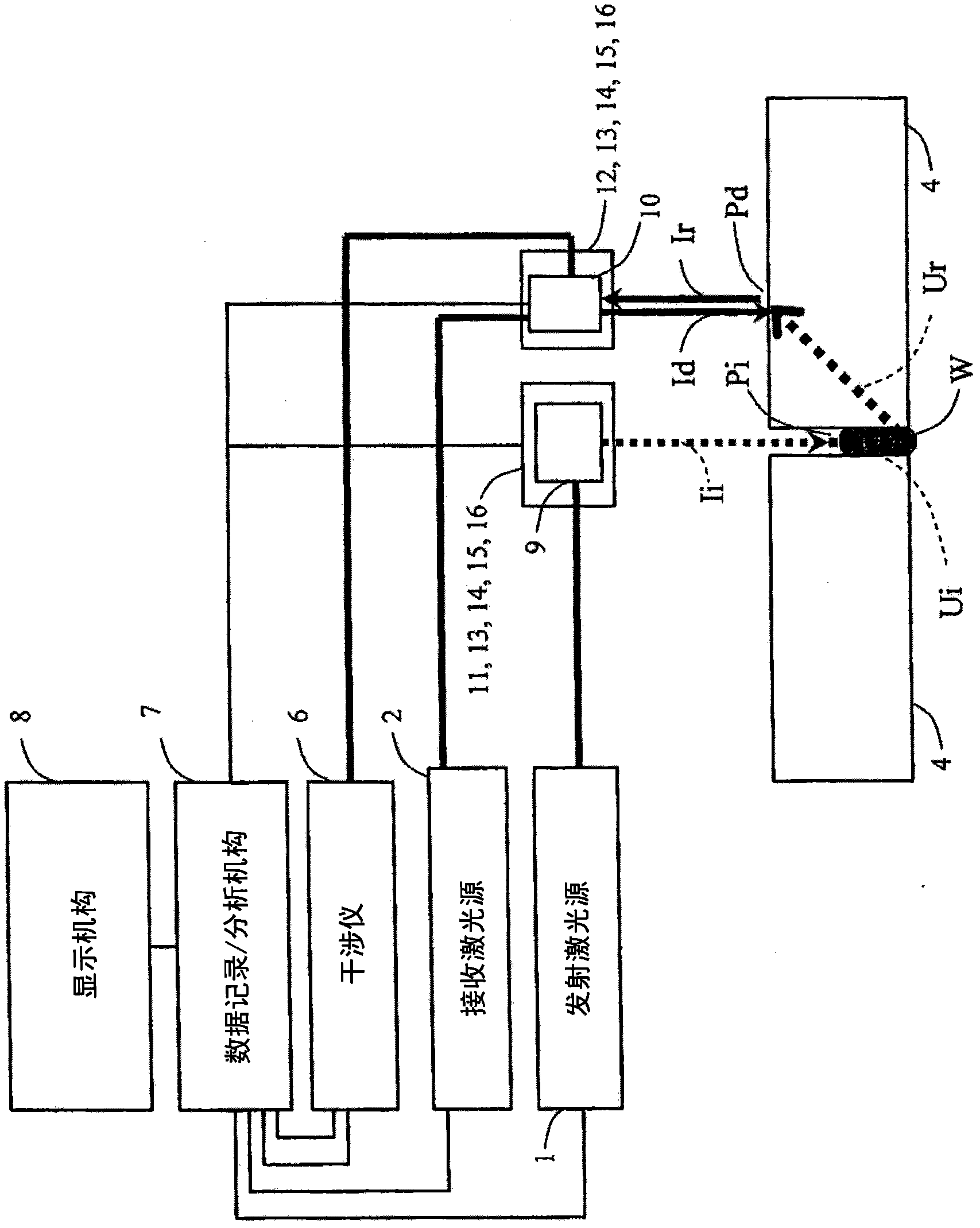
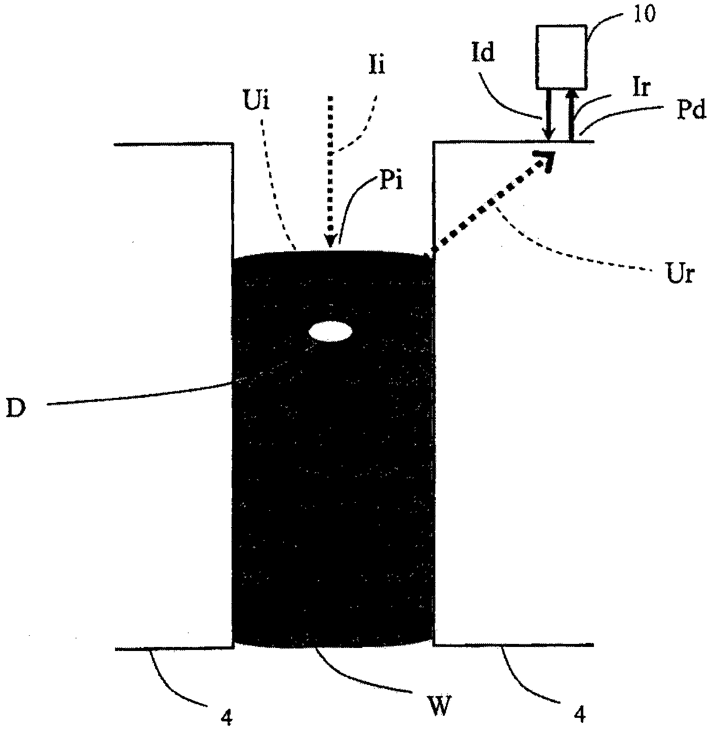
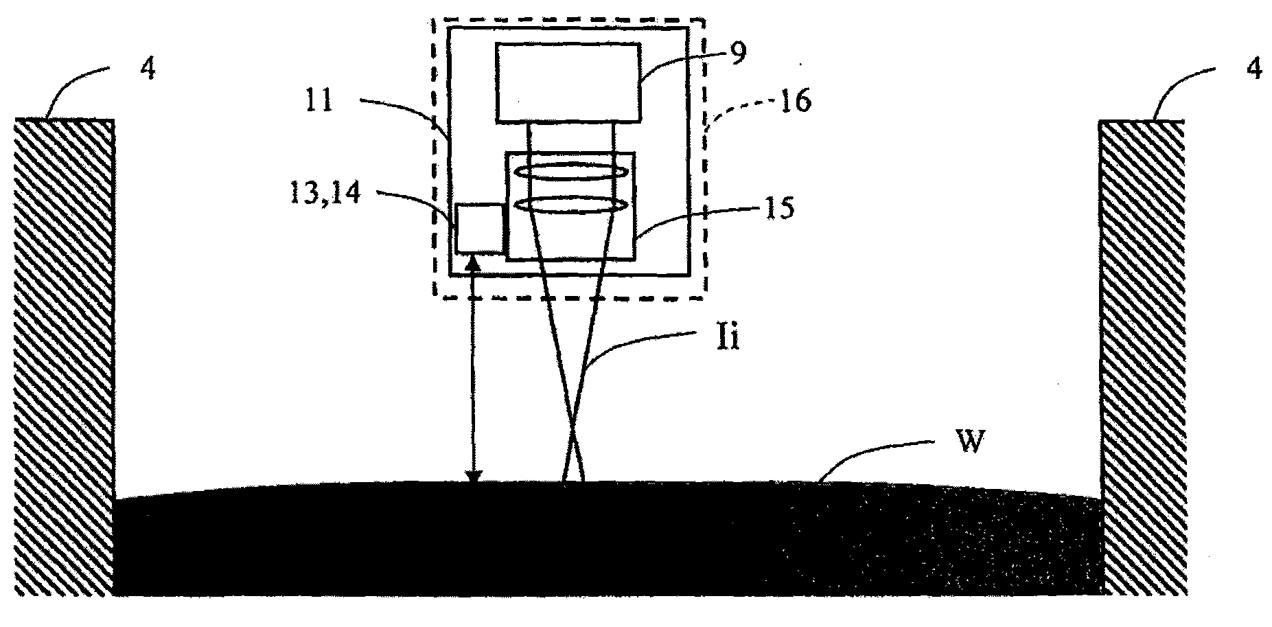
[0044] figure 1 Shown is a schematic block diagram of the configuration of the welding inspection apparatus according to the first embodiment of the present invention. figure 2 Shown is a cross-sectional view of paths of emitted laser light, received laser light, scattered / reflected laser light, and excited ultrasonic waves in the welding inspection method according to the first embodiment of the present invention. image 3 A sectional view for explaining the functions of the distance measuring mechanism and the focus control mechanism in the out-of-focus state in the welding inspection method according to the first embodiment of the present invention. Figure 4 A sectional view for explaining the functions of the distance measuring mechanism and the focus control mechanism in the in-focus state in the welding inspection method according to the first embodiment of the present invention.
[0045] The welding inspection device according to the present embodiment includes: an e...
no. 2 example
[0067] Image 6 Shown is a schematic block diagram of a configuration of a welding inspection apparatus according to a second embodiment of the present invention. Figure 7 Shown is a cross-sectional view of paths of emitted laser light, received laser light, scattered / reflected laser light, and excited ultrasonic waves in a welding inspection method according to a second embodiment of the present invention.
[0068] In this embodiment, the receiving laser light Id is irradiated to the groove side surface. In this case, the incident ultrasonic wave Ui directly enters the defect D directly below the incident point, and the reflected ultrasonic wave Ur from the defect D propagates within the object 4 to be inspected as a bulk wave such as a longitudinal wave or a transverse wave. The surface wave component whose mode has been converted at the groove portion is irradiated on the receiving laser light Id on the groove side surface for reception. This enables defect inspection of...
no. 3 example
[0072] Figure 8 Shown is a schematic block diagram of a configuration of a welding inspection apparatus according to a third embodiment of the present invention. In this embodiment, the positional relationship between the emitting laser irradiation point Pi and the receiving laser irradiation point Pd in the first embodiment is reversed so that the receiving laser irradiation point Pd is on the surface of the welded metal part W of the object 4 to be inspected. superior. Other than that, other configurations are the same as those of the first embodiment. Even if the positions of the emitting laser irradiation point Pi and the receiving laser irradiation point Pd are reversed, the systematic effect can be obtained.
PUM
| Property | Measurement | Unit |
|---|---|---|
| thickness | aaaaa | aaaaa |
Abstract
Description
Claims
Application Information
 - R&D
- Intellectual Property
- Life Sciences
- Materials
- Tech Scout
- Unparalleled Data Quality
- Higher Quality Content
- 60% Fewer Hallucinations
Browse by: Latest US Patents, China's latest patents, Technical Efficacy Thesaurus, Application Domain, Technology Topic, Popular Technical Reports.
© 2025 PatSnap. All rights reserved.Legal|Privacy policy|Modern Slavery Act Transparency Statement|Sitemap|About US| Contact US: help@patsnap.com