
Electric injection ignition debugging device for motorcycle engine and control method thereof

An ignition control, engine technology, applied in the direction of engine control, electrical control, engine components, etc., can solve the problems of incomplete information display, rough control method, complex circuit structure, etc., to improve control accuracy, improve anti-interference ability, control The effect of strict logic

Inactive Publication Date: 2012-01-18
GUANGDONG IND TECHN COLLEGE
View PDF4 Cites 2 Cited by
  • Summary
  • Abstract
  • Description
  • Claims
  • Application Information

AI Technical Summary

Problems solved by technology

However, the existing devices still have the following disadvantages: 1) the circuit structure is complex, the existing devices use A / D modules to realize signal conversion processing, use combination buttons to set parameters, and some devices even use 2 single-chip microcomputers for processing; 2) the control method is rough , the function is relatively single, the existing device only adjusts the ignition advance angle according to the engine speed; 3) the information display is incomplete, some existing devices use LED digital tubes as the display module and can only display simple digital information, even if some devices use LCD liquid crystal display modules , and only display the speed and ignition timing information, it is impossible to provide users with enough information to optimize the operating parameters of the engine EFI ignition control system

Method used


Image

  • Electric injection ignition debugging device for motorcycle engine and control method thereof
  • Electric injection ignition debugging device for motorcycle engine and control method thereof
  • Electric injection ignition debugging device for motorcycle engine and control method thereof

Examples


Embodiment 1

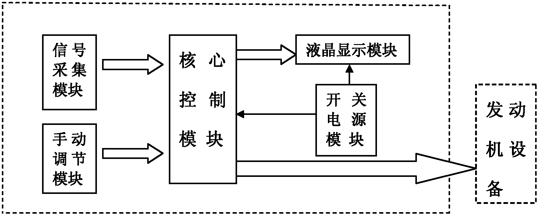
[0040] Such as figure 1 As shown, a motorcycle engine EFI ignition debugging device, including: a signal acquisition module, used to collect the current ambient temperature, and further calculate the speed and control the fuel injection pulse width, ignition delay angle, air intake volume for the core control module Provide relevant signals of the engine;

[0041] The core control module is used to analyze and process the acquired external signals according to different working modes, control the fuel injection pulse width, ignition delay angle, air intake volume according to the setting value of the manual adjustment knob or the determined control logic, and Send the processed data and collected raw data to the liquid crystal display module;

[0042] The liquid crystal display module is used for real-time display of the data transmitted by the core control module;

[0043] The manual adjustment module is used to manually adjust the ignition delay angle and fuel injection pu...


PUM


Abstract

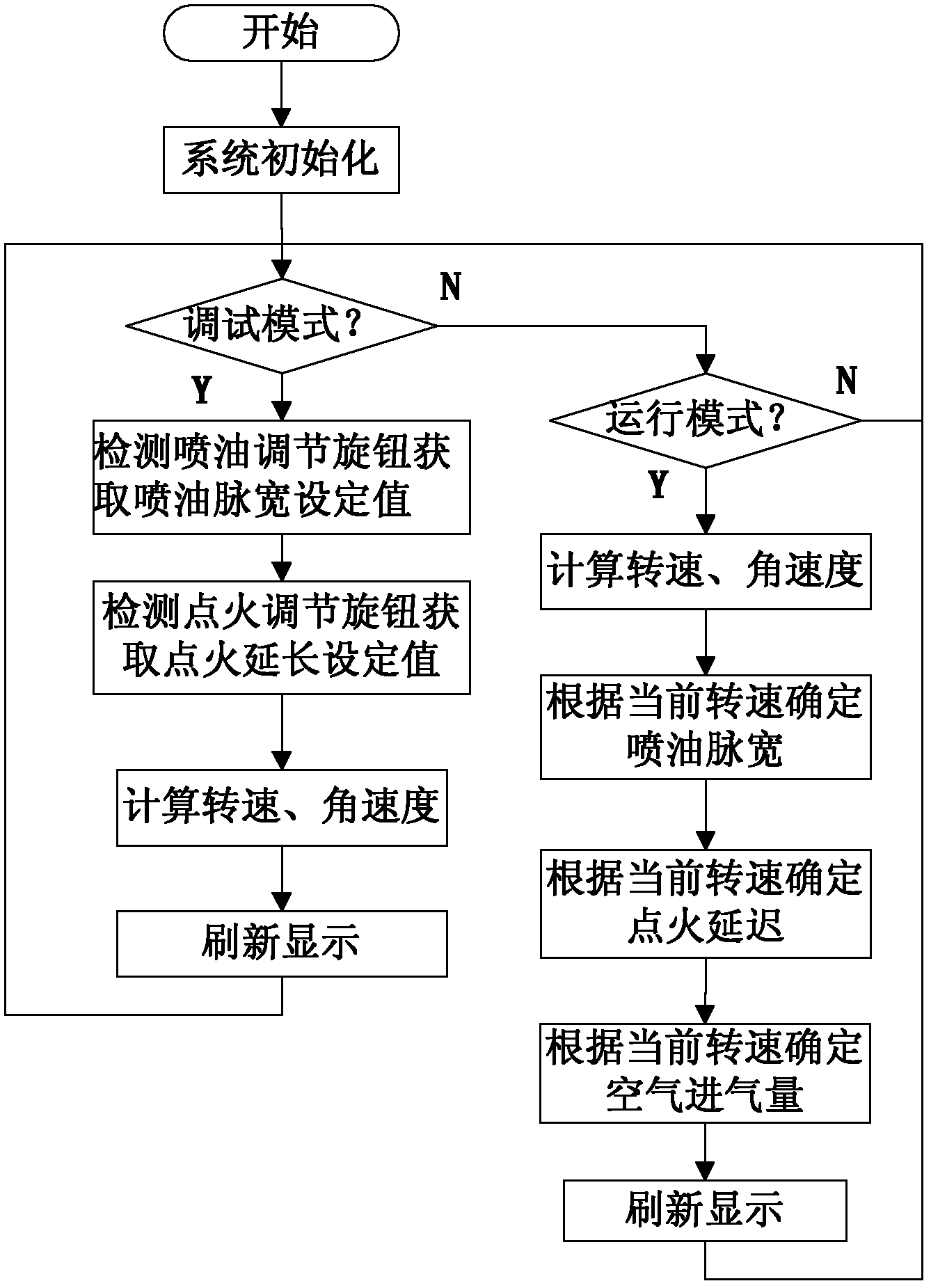
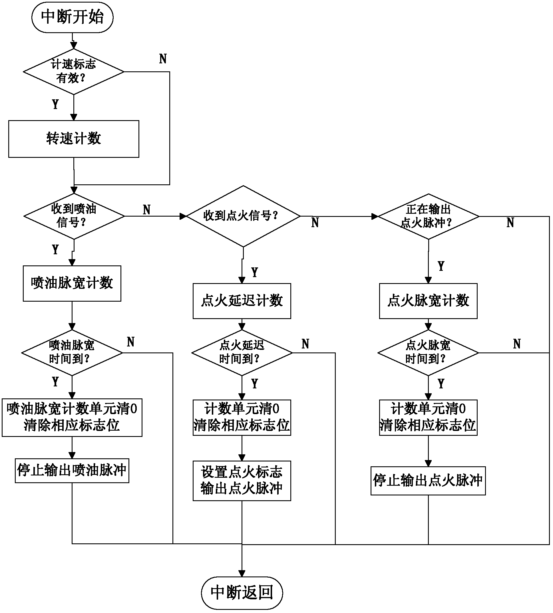
The invention discloses an electric injection ignition debugging device for a motorcycle engine and a control method thereof. The device comprises a core control module and a signal acquisition module, a liquid crystal display module, a manual regulating module and a switching power supply module which are connected with the core control mode. The switching power supply module is also connected with the liquid crystal display module. The core control module is connected with external engine equipment. The method comprises the following steps of: starting the engine by the core control module according to a preset initial value; then respectively carrying out treatment according to a selected working mode; in a debugging mode, determining a set of engine electric injection ignition control logic by mutual action of the manual regulating module, the core control module and the liquid crystal display module; and in an operating mode, determining an ignition delay angle, an oil injection pulse width with and an air input according to a rotating speed and the control logic. The electric injection ignition debugging device for the motorcycle engine and the control method thereof have various advantages of high ignition accuracy, strong adaptive control capacity, strong anti-interference capacity and the like.

Description

technical field [0001] The invention belongs to the design field of an engine electronic injection ignition control system, in particular to a motorcycle engine electronic injection ignition debugging device and a control method thereof. Background technique [0002] The EFI system inputs signals such as engine temperature, throttle status, engine speed, and crankshaft position to the microcontroller through various sensors. The microcontroller analyzes, calculates and judges the signals, and accurately controls and selects the best ignition and ignition. The fuel injection timing and fuel injection quantity ensure that the engine always works in the best condition. [0003] Compared with the traditional mechanical system control engine, the EFI engine has the outstanding advantage that it can accurately control the quality of the mixed gas, ensure the complete combustion of the fuel in the cylinder, and reduce the exhaust emissions and fuel consumption accordingly. The cha...

Claims


Application Information

Patent Timeline
Patent Type & Authority Applications(China)
IPC IPC(8): F02D43/00F02B77/08
Inventor 彭选荣黄晓红章劲松
Owner GUANGDONG IND TECHN COLLEGE
Learn More