
Cover opening and closing safety device of pressure cooker

A safety device, a technology for opening and closing lids, applied in pressure cookers, cooking utensils, household appliances, etc., can solve the problems of unclean pressure removal in the pot, complex structure, inconvenient use, etc., and achieve shortened cooking time, high sensitivity, and reduced The effect of energy consumption

Active Publication Date: 2013-11-06
ZHEJIANG SUPOR CO LTD
View PDF4 Cites 43 Cited by
  • Summary
  • Abstract
  • Description
  • Claims
  • Application Information

AI Technical Summary

Problems solved by technology

[0004] But above-mentioned pressure cooker double-card safe opening and closing lid safety valve has more parts, and structure is comparatively complicated, and the installation of upper card, lower card, upper card slider and lower card slider at the handle place is also comparatively difficult; The upper card and the lower card are sealed, the float valve is not connected to the outside world, the air pressure in the pot is not completely removed, and it takes a lot of force to close the lid until the end, which is inconvenient to use

Method used


Image

  • Cover opening and closing safety device of pressure cooker
  • Cover opening and closing safety device of pressure cooker
  • Cover opening and closing safety device of pressure cooker

Examples


Embodiment 1

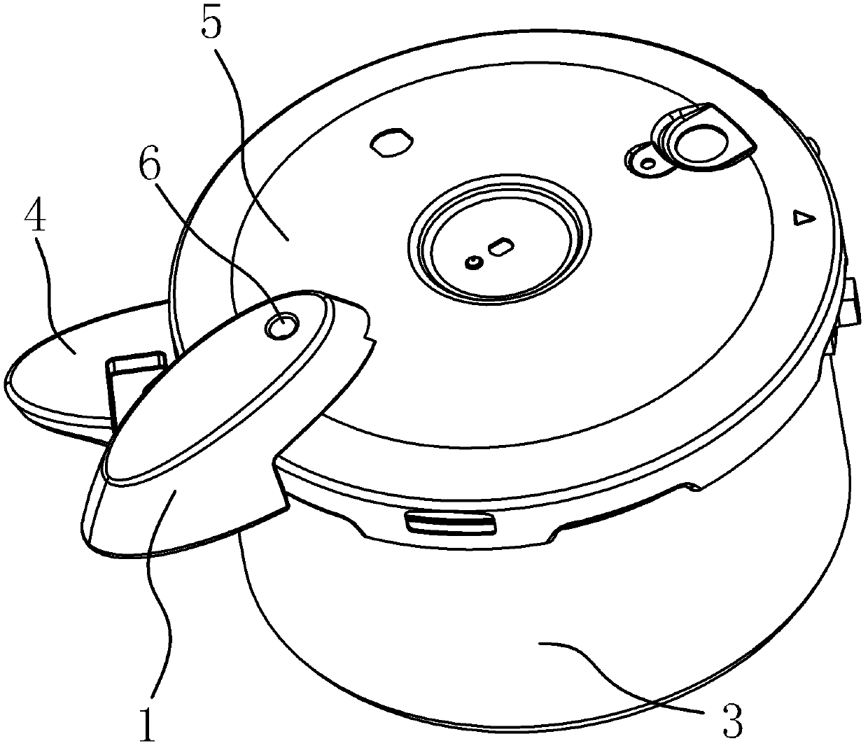
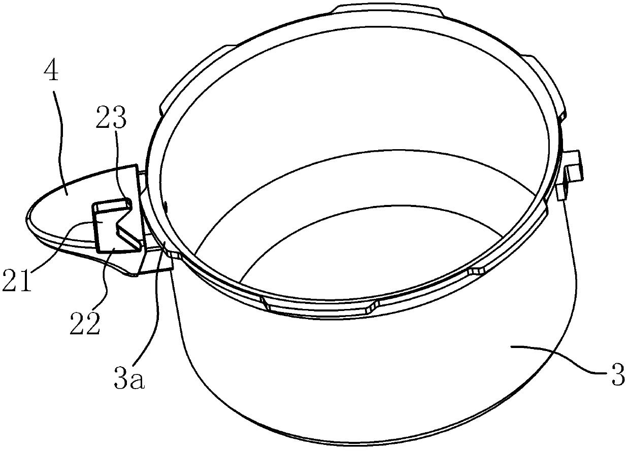
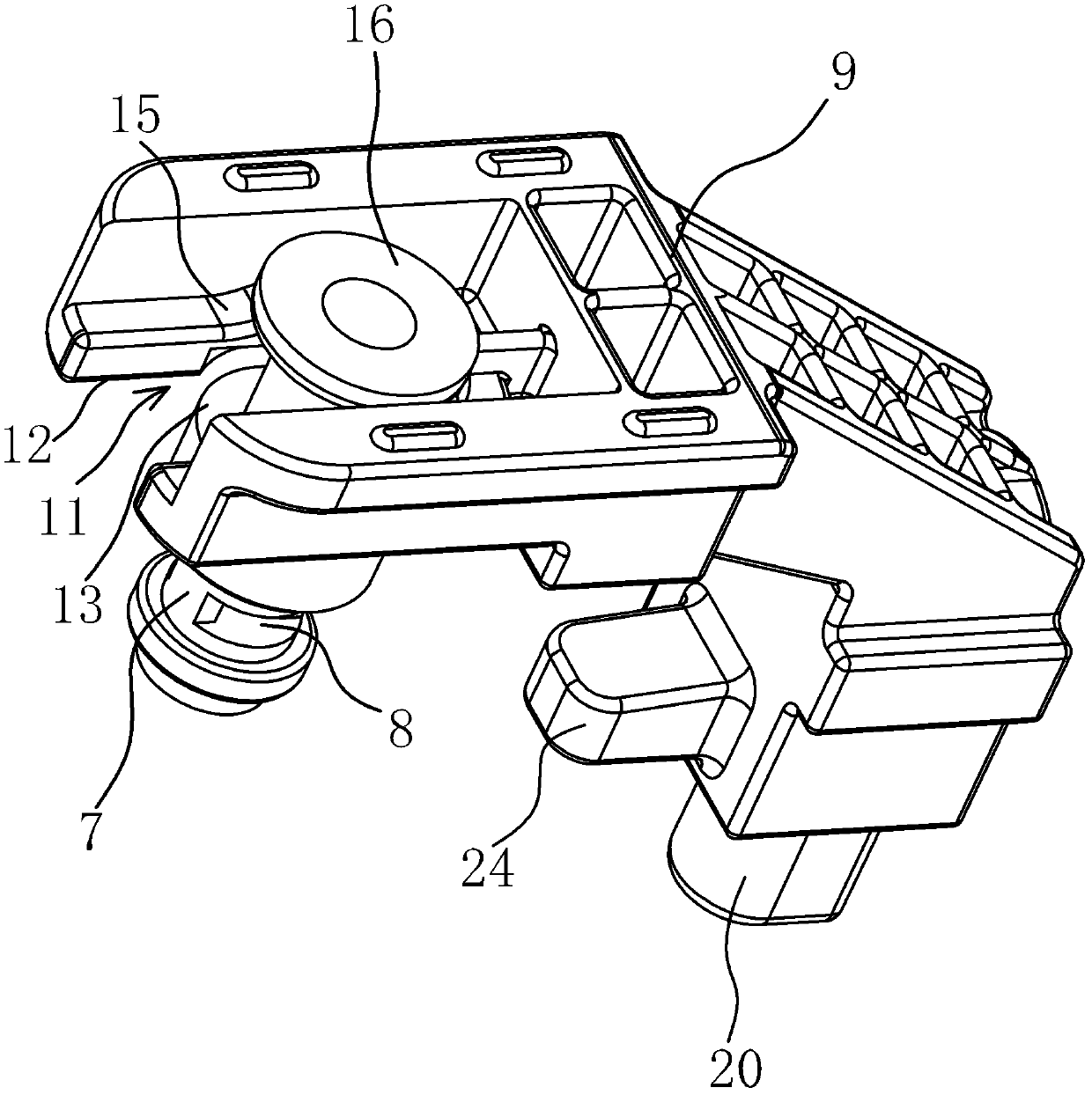
[0036] Such as figure 1 , figure 2 with Image 6 As shown, the safety device for opening and closing the lid of the pressure cooker includes an upper handle 1, a valve seat 2 and a lower handle 4 fixed on the pot body 3. The pot mouth of the pot body 3 has an outwardly turned edge 3a, and the upper handle 1 It is fixed on the pot cover 5 and the upper handle 1 has a through hole 6 communicating with the outside world. The valve seat 2 is fixed on the pot cover 5 and the valve seat 2 is pierced with a non-opening valve stem 7 that can be raised and lowered. The inner end located at the inside of the pot cover 5 is provided with an exhaust hole 8 communicating with the through hole 6, and the upper handle 1 is provided with a push plate 9 that can slide close to or away from the edge of the pot cover 5, and the push plate 9 and the upper handle 1 A spring 10 with one end against the upper handle 1 and the other end against the push plate 9 is arranged between them. In order ...

Embodiment 2

[0043] Such as Figure 9 As shown, the structure and principle of this embodiment are basically the same as that of Embodiment 1. The difference lies in that the lifting structure in this embodiment includes a top block 17 on the upper part of the bayonet 11 and a peripheral edge at the outer end of the valve stem 7. To the raised lifting block 18 , the contact surface of the lifting block 18 and the top block 17 is a slope 19 , and the slope 19 is inclined downward from the inside of the bayonet 11 toward the end. When the push plate 9 approaches the pot body 3 under the elastic force of the spring 10, the top block 17 touches the slope 19 of the lifting block 18, so that the lifting block 18 drives the stop valve stem 7 to rise together until the stop valve stem The exhaust hole 8 of 7 is located on the sealing surface of the valve seat 2.


PUM


Abstract

The invention relates to a pressure cooking device comprising: - a vessel and a lid to form a cooking chamber, - a first port, - an opening safety means movable between a release position and a locking position, said opening safety means being designed to be in the locking position when the pressure inside the chamber is greater than or equal to a pre-determined value referred to as the rising pressure, characterised in that said opening safety means is designed to pass through a first intermediate position in which it releases said first port when it moves in either direction between said release and locking positions, , said device comprising an actuating means (13) for actuating the opening safety means, designed to allow the opening safety means to be moved into its first intermediate position. Pressure cooking devices.

Description

technical field [0001] The invention belongs to the technical field of cooking utensils, and relates to a pressure cooker, in particular to a safety device for opening and closing the lid of the pressure cooker. Background technique [0002] In order to make the pressure cooker can be used normally and safely, a safety device is provided on the hook of the opening and closing cover of the pressure cooker at present. When the lid of the pressure cooker is not fastened to the body of the pressure cooker, the safety device prevents the pressure inside the pot from rising; when the pressure cooker is used and the lid is opened, if there is still pressure in the pot, the safety device prevents the lid from being opened. [0003] At present, there are many types of installation devices for pressure cooker opening and closing lids, and the specific operations are also different during use. Many safety devices have also applied for patents. For example, Chinese patent literature dis...

Claims


Application Information

Patent Timeline
Patent Type & Authority Patents(China)
IPC IPC(8): A47J27/09
CPCA47J27/092
Inventor 罗权金伟平郑祖福
Owner ZHEJIANG SUPOR CO LTD
Learn More