
Vehicle-mounted high-power liquid cooling equipment

A liquid cooling and high-power technology, which is applied in the direction of cooling/ventilation/heating transformation, etc., can solve the problems of equipment power limit, lack of heating function, and affect the normal operation of the system, so as to increase the cooling power, ensure versatility, Ease of transport

Active Publication Date: 2012-01-11
西安飞豹科技有限公司
View PDF3 Cites 6 Cited by
  • Summary
  • Abstract
  • Description
  • Claims
  • Application Information

AI Technical Summary

Problems solved by technology

At present, the power of ground high-power radar and airborne early warning aircraft radar exceeds 100kW. The commonly used forced air cooling can no longer meet the heat dissipation requirements of these electronic equipment, which affects the normal operation of the system. Liquid cooling is required to cool electronic equipment.
However, most of the existing liquid-cooling equipment is some small-scale liquid-cooling test equipment, which can no longer meet the cooling requirements of high-power electronic equipment in terms of liquid supply flow, heat dissipation power, and equipment versatility, and the power supply of the equipment is limited. When using external power, it does not have a heating function when used in a low-temperature environment in winter, and cannot provide cooling fluid that meets the temperature requirements.

Method used


Image

  • Vehicle-mounted high-power liquid cooling equipment
  • Vehicle-mounted high-power liquid cooling equipment
  • Vehicle-mounted high-power liquid cooling equipment

Examples


Embodiment Construction

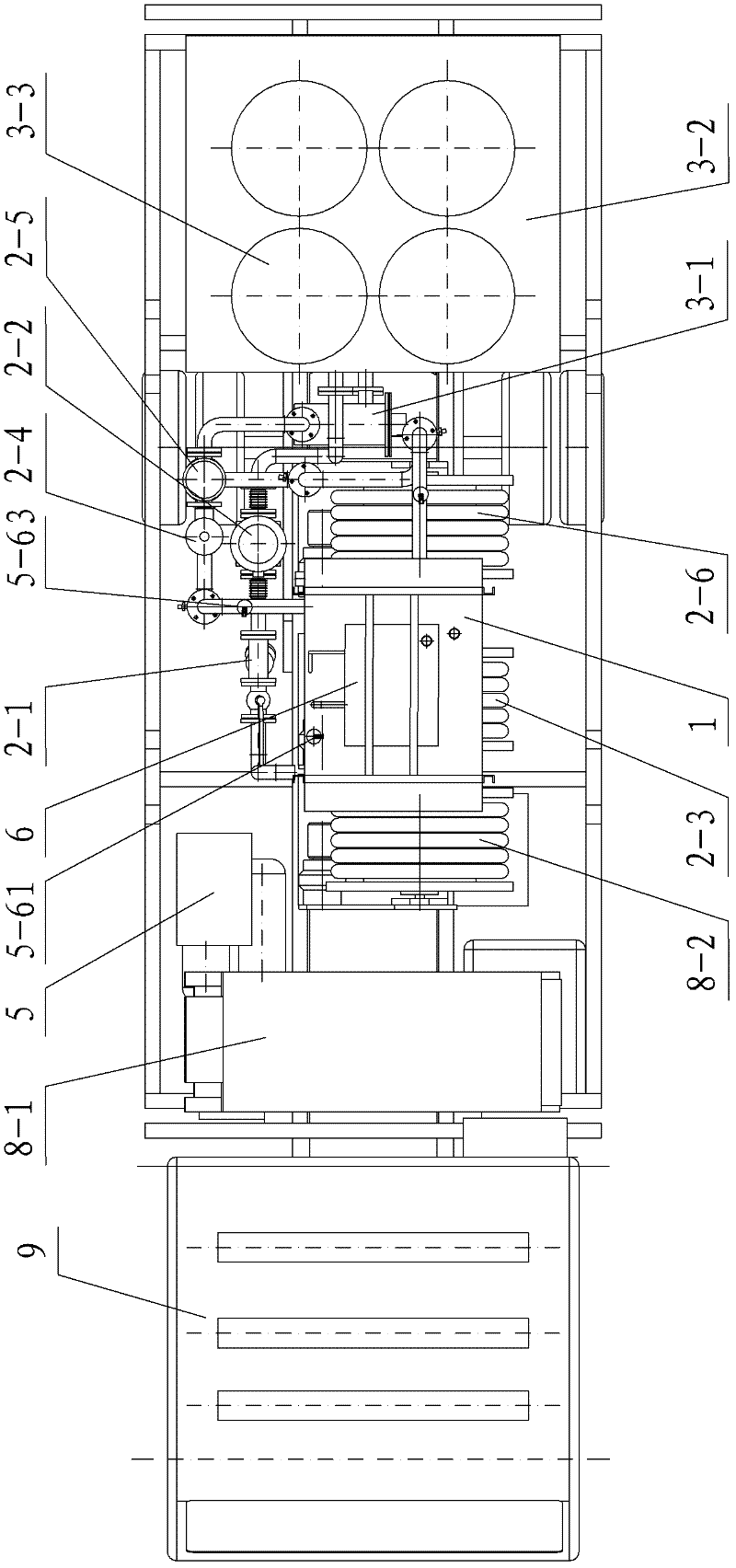
[0047] Such as figure 1 , figure 2 and Figure 5 As shown, the present invention includes a liquid storage tank 1, a cooling circulation system connected with the liquid storage tank 1, a temperature regulation system connected with the cooling circulation system, a cooling circulation system connected with the temperature regulation system and used to control the cooling cycle The electrical control system for system and temperature adjustment system work, and the power supply system for cooling circulation system, temperature adjustment system and electrical control system; The liquid supply system of the electronic device 10 and the liquid return system that realizes the return of liquid from the electronic device 10 to be cooled to the liquid storage tank 1, the liquid supply system includes a liquid outlet connected to the liquid storage tank 1 and a liquid inlet of the temperature adjustment system Between the filter 2-1 and the liquid suction pump 2-2, the liquid sup...


PUM


Abstract

The invention discloses vehicle-mounted high-power liquid cooling equipment, which comprises a liquid storage box, a cooling circulation system, a temperature regulation system, an electric control system and a power supply system, wherein the temperature regulation system comprises a refrigeration system and a pipeline electric heater, the refrigeration system comprises two groups of condenser sets and an air cooling heat radiator, the air cooling heat radiator is connected in series with two groups of condenser sets connected in parallel into a whole, the cooling circulation system comprises a liquid supply system and a liquid return system, the liquid supply system comprises a filter, a liquid pumping pump, a liquid supply hose, a precise filter and a first flow rate regulation three-way valve, the filter and the liquid pumping pump are connected between a liquid discharge opening of the liquid storage box and a liquid inlet opening of the refrigeration system, the liquid supply hose is connected between the liquid discharge opening of the refrigeration system and the liquid inlet opening of the electronic equipment to be cooled, the precise filter and the first flow rate regulation three-way valve are arranged on the liquid supply hose, and the liquid return system comprises a liquid return hose connected between the liquid discharge opening of the electronic equipment to be cooled and the liquid inlet opening of the liquid storage box. The vehicle-mounted high-power liquid cooling equipment has the advantages that the design is reasonable, the refrigeration power is high, the energy is saved, the efficiency is high, the stability and the reliability are high, the intelligent degree is high, the use and the operation are convenient and fast, and the popularization and the application are convenient.

Description

technical field [0001] The invention relates to cooling equipment, in particular to a vehicle-mounted high-power liquid cooling equipment. Background technique [0002] When any electronic mission system is working, it will generate a lot of heat, especially high-power components, which generate more concentrated heat. At present, the power of ground high-power radar and airborne early warning aircraft radar exceeds 100kW. The commonly used forced air cooling can no longer meet the heat dissipation requirements of these electronic equipment, which affects the normal operation of the system. Liquid cooling is required to cool electronic equipment. However, most of the existing liquid-cooling equipment is some small-scale liquid-cooling test equipment, which can no longer meet the cooling requirements of high-power electronic equipment in terms of liquid supply flow, heat dissipation power, and equipment versatility, and the power supply of the equipment is limited. When usin...

Claims


Application Information

Patent Timeline
Patent Type & Authority Applications(China)
IPC IPC(8): H05K7/20
Inventor 王小军夏齐吴亮林朋孟辉龙
Owner 西安飞豹科技有限公司
Learn More