Oil-quenching air-cooling vacuum furnace

A vacuum furnace and oil quenching technology, applied in quenching devices, heat treatment equipment, manufacturing tools, etc., can solve problems affecting quality, inconvenient processing of workpieces, shaking of workpiece cars, etc., to achieve convenient operation, simple structure, and reduce shaking or derailment Effect

Inactive Publication Date: 2012-01-11
太仓市华瑞真空炉业有限公司
View PDF6 Cites 3 Cited by
  • Summary
  • Abstract
  • Description
  • Claims
  • Application Information

AI Technical Summary

Problems solved by technology

At present, the oil-quenched air-cooled vacuum furnace generally includes the furnace body, the conveying mechanism of the workpiece, the vacuum system, the cooling system, the electric control system, and the oil quenching processing system. However, the conveying mechanism of the workpiece includes the movement of the workpiece in the horizontal direction and the vertical direction. The conveying mechanism in the vertical direction generally adopts a jack or hydraulic forklift, but the driving mechanism of the jack or hydraulic forklift is relatively complicated, and the production cost is relatively high. At the same time, the conveying mechanism in the horizontal direction generally adopts a single-track conveying device. Entering the processing area of ​​the oil quenching furnace, however, when the workpiece is large in size or heavy in weight, the workpiece car is likely to shake or fall off the track, which brings great inconvenience to the processing of the workpiece and affects the quality of the workpiece after processing

Method used


Image

  • Oil-quenching air-cooling vacuum furnace
  • Oil-quenching air-cooling vacuum furnace
  • Oil-quenching air-cooling vacuum furnace

Examples


Embodiment Construction

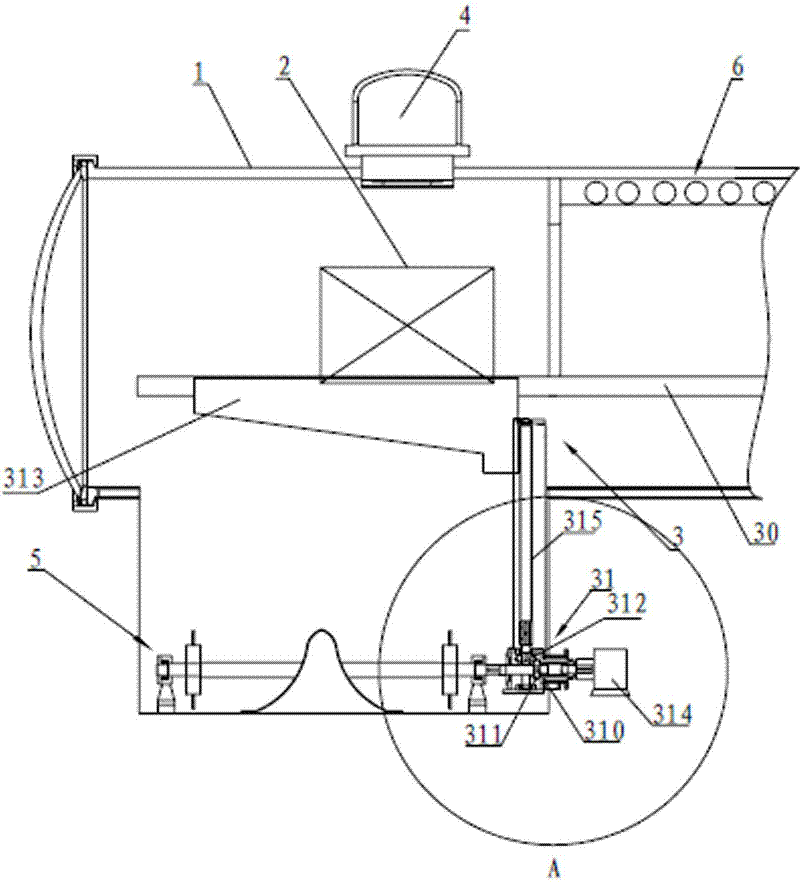
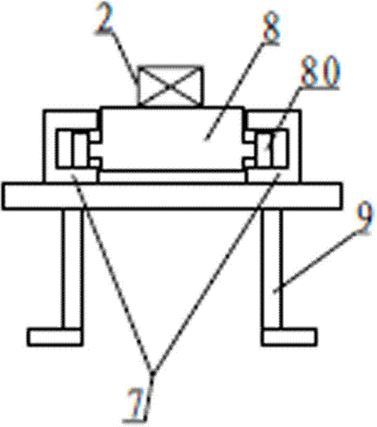
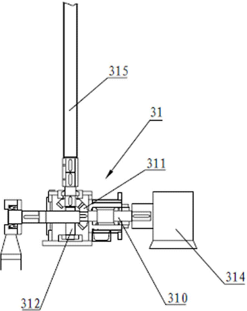
[0016] Such as figure 1 As shown, the oil-quenched air-cooled vacuum furnace according to this embodiment includes a furnace body 1, a conveying mechanism 3 for workpieces 2, a vacuum system 4, an oil-quenched processing system 5, a cooling system 6, and an electric control system (not shown in the figure) ), the conveying mechanism 3 includes a conveying device 30 in the horizontal direction of the workpiece 2 and a lifting device 31 in the vertical direction, wherein the conveying device 30 includes a double slide rail 7 and a double slide rail 7 arranged in the furnace body 1 for conveying the workpiece 2 Cooperating workpiece trolley 8 and rail support 9 for supporting double sliding track 7 and being fixed in the body of furnace 1, lifting device 31 comprises the first worm screw 310 that is arranged on the side bottom of body of furnace 1, and the first worm screw 310 phase Cooperating worm gear 311, the second worm screw 312 that cooperates with worm gear 311, the pl...


PUM


Abstract

The invention relates to an oil-quenching air-cooling vacuum furnace, which comprises a body of furnace, a conveying mechanism of workpieces, a vacuum system, an oil-quenching processing system, a cooling system and an electric control system. The conveying mechanism comprises a device for horizontally conveying workpieces and a device for vertically lifting workpieces, wherein the conveying device comprises double slide tracks for conveying workpieces which are arranged in the body of furnace, a trammer for workpieces which is cooperated with double slide tracks and a track support used for supporting the double slide tracks and fixed in the furnace. The double slide tracks are used for minimizing the phenomenon of shaking or derailing of workpieces, so that the workpieces can be sent to a processing zone or moved out of the furnace body steadily, in addition, by the cooperation of worm gear with a first worm and a second worm, a screw which is cooperated with a workpiece platform is provided on the second worm, the rotation of the screw drives the platform to move along the screw length direction up and down to realize the vertical lifting of the workpieces. The structure is simple and the operation is convenient.

Description

technical field [0001] The invention relates to an oil-quenched air-cooled vacuum furnace. Background technique [0002] Oil-quenching air-cooled vacuum furnace is mainly used for bright quenching of alloy steel, alloy structural steel, tool and die steel, spring steel, bearing steel, stainless steel, precision alloy steel and other materials, as well as sintering, bright annealing and vacuum brazing of magnetic materials. At present, the oil-quenched air-cooled vacuum furnace generally includes the furnace body, the conveying mechanism of the workpiece, the vacuum system, the cooling system, the electric control system, and the oil quenching processing system. However, the conveying mechanism of the workpiece includes the movement of the workpiece in the horizontal direction and the vertical direction. The conveying mechanism in the vertical direction generally adopts a jack or hydraulic forklift, but the driving mechanism of the jack or hydraulic forklift is relatively com...

Claims


Application Information

Patent Timeline
Patent Type & Authority Applications(China)
IPC IPC(8): C21D1/63C21D1/773
Inventor 郑铁克
Owner 太仓市华瑞真空炉业有限公司
Why Eureka
Try Eureka