
Fastener element for concealed slide fasteners

A technology for zippers and chain teeth, applied in the direction of sliding fastener components, applications, fasteners, etc., can solve the problems of easy damage, beautiful appearance, flying broken pieces, increased operation and material costs, etc.

Inactive Publication Date: 2014-04-09
YKK CORP
View PDF3 Cites 0 Cited by
  • Summary
  • Abstract
  • Description
  • Claims
  • Application Information

AI Technical Summary

Problems solved by technology

[0004] However, in such invisible slide fasteners, there is usually a problem that when tensile stress is applied from both sides of the fastener tape in the tape width direction when the elements are meshed, a gap is generated between the left and right fastener tapes, resulting in The meshed elements can be seen from the surface side of the belt, and concealment cannot be ensured
However, when such fragile threads or plastic components are used, it is easy to damage the appearance of the car seat. In particular, when using fragile threads, it is necessary to sew a low-elasticity cloth on the back of the skin of the unfolded part of the seat. , which not only increases the complexity of seat manufacturing, but also may increase the cost of operation and materials
In addition, when fragile plastic components are used, when the unfolded part of the seat cover is unfolded, the plastic components are easily broken and the broken pieces are scattered to the surrounding area.

Method used


Image

  • Fastener element for concealed slide fasteners
  • Fastener element for concealed slide fasteners
  • Fastener element for concealed slide fasteners

Examples


Embodiment 1

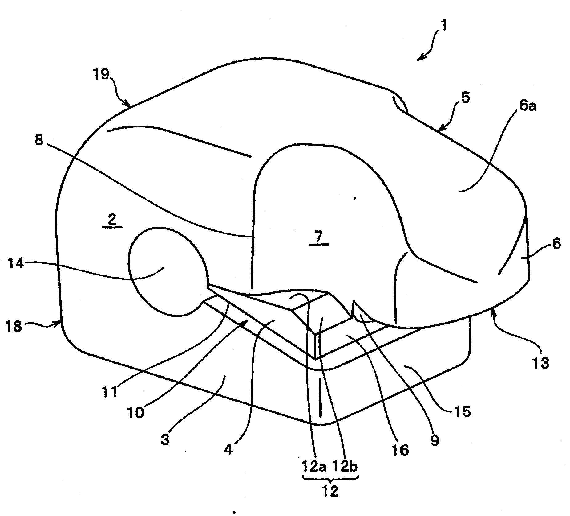
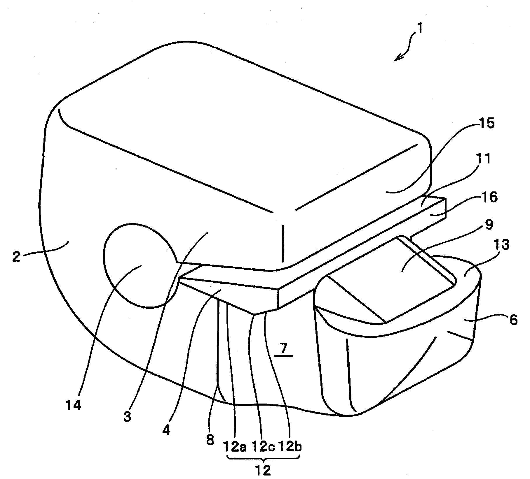
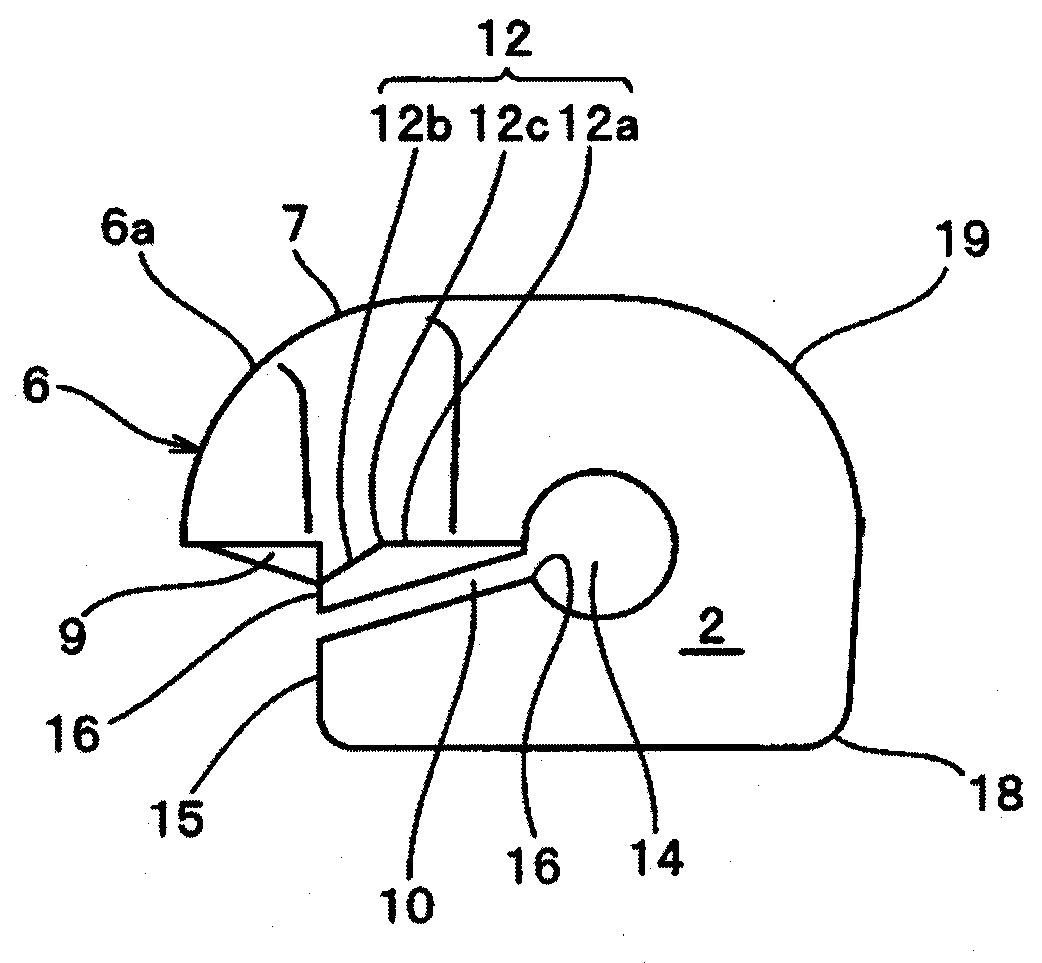
[0053] figure 1 It is a perspective view viewed from the element exposure side showing the entire fastener element of the first embodiment of the present invention, figure 2 is a perspective view of the zipper element viewed from the hidden side of the element, image 3 is a side view of the zipper element. in addition, Figure 4 is a side view of the state where the zipper elements are engaged, Figure 5 It is a side view which shows the state at the time of disengagement when the lateral pull force of the fastener tape of left and right acts on this meshing fastener element. Figure 6 yes Figure 5 The enlarged section view of the main part.

[0054] The fastener element 1 is formed to have a tape side edge mounting groove 10 for attaching the tape side edge of the fastener tape 22 in a substantially U-shape as a whole, and the fastener element 1 has a string portion that holds the fastener tape 22 The C-shaped base 2 of 25, the flat plate-shaped first band clamping p...

Embodiment 2

[0067] Figure 6 The 2nd Example of the fastener element of this invention is shown. Also in this Example, the structure of the main part of the fastener element 1 does not substantially change from the said 1st Example. The characteristic structure in this embodiment lies in the point that the relative dimensional relationship between the engaging head 6 and the neck 7 of the fastener element 1 is defined. Therefore, in the following description, the same names and reference numerals are used for the names and reference numerals of parts substantially corresponding to those of the above-mentioned first embodiment.

[0068] Such as Figure 6 As shown, the engaging portion 5 of the fastener element 1 has a neck portion 7 and an oval engaging head portion 6 in plan view, and the neck portion 7 becomes thinner in the center from the long diameter portion of the engaging head portion 6 and becomes C-shaped. A shoulder 8 extends from the top face of the base 2 and the neck 7 is ...

Embodiment 3

[0071] Figure 7 and Figure 8 A fastener element for a concealed slide fastener according to a third embodiment of the present invention and its state during rotation are shown.

[0072] In this embodiment, the difference from the above-mentioned first and second embodiments is that, compared with the first embodiment and the second embodiment, the engaging surface 12 of the second belt clamping portion 4 is in surface contact with each other. The upper surface 13 ( figure 2 upper surface) is formed as a plane, and the upper surface 13 and the elliptical peripheral side are orthogonal to each other, in this embodiment, as Figure 7 and Figure 8 As shown, at least the ridgeline portion of the top end of the engaging head 6 is perpendicular to the engaging direction to form a chamfered portion 6b. As the chamfered portion 6b, the case where it is set as a curved surface can be cited, but it may also be as Figure 13 Shown is an inclined surface sloping towards the top en...


PUM


Abstract

A fastener element for concealed slide fasteners includes a C-shaped root portion (2) having a generally U shape with a groove (10) into which the side edge of a fastener tape (22) is fitted and a circular holding hole (14) defined in the central part thereof for holding a core cord (25), first and second flat tape-holding parts (3, 4) extending from the ends of the C-shaped root portion (2) generally parallel to each other, and a meshing portion (5) formed integrally with the engaging surface (12) of the back surface opposite to the tape holding surface (11) of the second tape-holding part (4). The engaging surface (12) of the back surface of the second tape-holding part (4) and the meshing head part (6) of the mate are so formed as to be easily rotatable relatively around the center of the circular holding hole (14).

Description

technical field [0001] The present invention relates to a fastener element for a hidden sliding slide fastener in which the meshing elements cannot be seen from the tape surface when fastener elements (hereinafter, sometimes simply abbreviated as elements) attached along one end edge of a pair of fastener tapes mesh, and A concealed slide fastener in which the elements are lined up on the element attachment edge of the fastener tape bent in a U-shape. Background technique [0002] Conventionally, the zipper elements used in this invisible sliding zipper are installed on one end edge of the zipper tape along the element mounting edge portion provided with the rib portion by injection molding of synthetic resin or die-casting of zinc alloy. . [0003] The element used for this concealed slide fastener has a substantially U-shaped longitudinal section, and the meshing portion of the element formed at one end of the element is attached toward the inside of the fastener tape. I...

Claims


Application Information

Patent Timeline
Patent Type & Authority Patents(China)
IPC IPC(8): A44B19/08
CPCA44B19/08A44B19/34
Inventor 小岛昌芳
Owner YKK CORP
Learn More