
High-performance integrated electromagnetic interference (EMI) filter

A filter and high-performance technology, applied in the direction of electrical components, impedance networks, etc., can solve the problem of increasing the facing area of ​​the single-turn copper wire windings on both sides of the dielectric board in the differential mode capacitor module, and the difficulty of integrating the differential mode capacitor value to reach the ideal value , increase the plane area of ​​the filter, etc., to achieve the effect of enhancing the ability to resist external electromagnetic interference, improving the utilization rate of the magnetic core, and increasing the insertion loss

Inactive Publication Date: 2012-01-04
NANJING UNIV OF AERONAUTICS & ASTRONAUTICS
View PDF4 Cites 10 Cited by
  • Summary
  • Abstract
  • Description
  • Claims
  • Application Information

AI Technical Summary

Problems solved by technology

[0004] However, the above-mentioned filters also have defects, the most serious of which is that the integrated differential mode capacitor value is difficult to achieve an ideal value, and there are two ways to overcome this defect: 1. Use high dielectric constant ceramic materials as the integrated differential mode capacitor module Dielectric board; 2. Increase the facing area of ​​the single-turn copper wire windings on both sides of the dielectric board in the differential mode capacitor module
Because ceramic materials with high dielectric constant have their own shortcomings, compared with most thin film dielectric materials, their dielectric constant stability with frequency and temperature changes is much worse. Approach 1 is obviously more difficult to achieve.
The realization of the second way is relatively simple, but the doubling of the facing area of ​​the copper wire winding will inevitably double the planar area of ​​the filter, which still needs to be improved.

Method used


Image

  • High-performance integrated electromagnetic interference (EMI) filter
  • High-performance integrated electromagnetic interference (EMI) filter
  • High-performance integrated electromagnetic interference (EMI) filter

Examples


Embodiment Construction

[0022] The technical solutions of the present invention will be described in detail below in conjunction with the accompanying drawings.

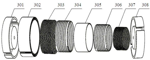
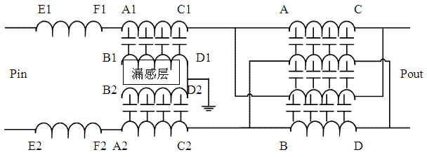
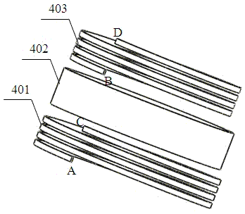
[0023] Such as Figure 1A As shown, the present invention provides a high-performance integrated EMI filter, including a first pot-type magnetic core 301, a differential mode capacitor 302, a first common mode inductor 303, a first integrated LC structure 304, and a leakage inductance arranged coaxially in sequence. layer 305, a second integrated LC structure 306, a second common-mode inductor 307, and a second can-shaped magnetic core 308. The first and second can-shaped magnetic cores 301, 308 can be interlocked to form an accommodating cavity, so that The rest of the parts are fastened in the accommodating cavity, and the first and second pot-type magnetic cores 301, 308 are all made of ferrite materials with a magnetic permeability of 2000-5000 (the magnetic permeability of 2000 is selected in this embodiment. ferrite material), its ef...


PUM


Abstract

The invention discloses a high-performance integrated electromagnetic interference (EMI) filter. The filter comprises a first can-shaped magnetic core, differential mode capacitor, a first common mode inductor layer, a first common mode integrated LC structure, a leakage inductance layer, a second common mode integrated LC structure, a second common mode inductor layer and a second can-shaped magnetic core which are coaxially arranged in turn. The first common mode inductor layer and a layer of coil of the first common mode integrated LC structure are forwards connected in series together by a conducting wire to form a forward coupling structure. The second common mode inductor layer and a layer of coil of the second common mode integrated LC structure are forwards connected in series together by a conducting wire to form another forward coupling structure. The first and second can-shaped magnetic cores are buckled with each other, and the parts arranged between the first and second can-shaped magnetic cores are buckled in an accommodation cavity. The differential mode capacitor is formed by alternately laminating a plurality of layers of cylinder wall-shaped ceramic plates and copper plates with nicks, and an innermost layer and an outermost layer are both the copper plates. The filter with such a structure can easily realize an ideal differential mode capacitance value, and the high-frequency filtering performance of the EMI filter is improved.

Description

technical field [0001] The invention relates to an integrated structure of an internal module of an EMI filter, in particular to a filter structure composed of cylinder-wall differential mode capacitors. Background technique [0002] Passive EMI filters are the main means to suppress conducted electromagnetic interference in switching power supplies, while traditional filters are composed of discrete inductors and capacitors. Due to the large number of discrete components, various shapes, and low space utilization, they occupy the entire converter. A large part of the volume of the system, and the parasitic parameters of the discrete components seriously affect the high frequency performance of the filter. Therefore, in order to reduce the size of the EMI filter and improve its high-frequency performance, it is very necessary to carry out research on integrated EMI filters. [0003] The integration of passive devices includes the integration of components such as transfor...

Claims


Application Information

Patent Timeline
IPC IPC(8): H03H9/46
Inventor 王世山朱叶石磊磊
Owner NANJING UNIV OF AERONAUTICS & ASTRONAUTICS
Learn More