
Three-dimensional entity model surface finite element mesh automatic generation method

A three-dimensional solid, automatic generation technology, applied in the field of engineering numerical analysis, can solve problems such as poor quality

Active Publication Date: 2012-01-04
SHANDONG UNIV
View PDF1 Cites 81 Cited by
  • Summary
  • Abstract
  • Description
  • Claims
  • Application Information

AI Technical Summary

Problems solved by technology

The grid method is more efficient in generating grids, but the generated surface grid is related to the orientation and size of the grid, and the quality of some cells in the grid may be poor

Method used


Image

  • Three-dimensional entity model surface finite element mesh automatic generation method
  • Three-dimensional entity model surface finite element mesh automatic generation method
  • Three-dimensional entity model surface finite element mesh automatic generation method

Examples


Embodiment Construction

[0080] The present invention will be further described below in conjunction with the accompanying drawings and embodiments.

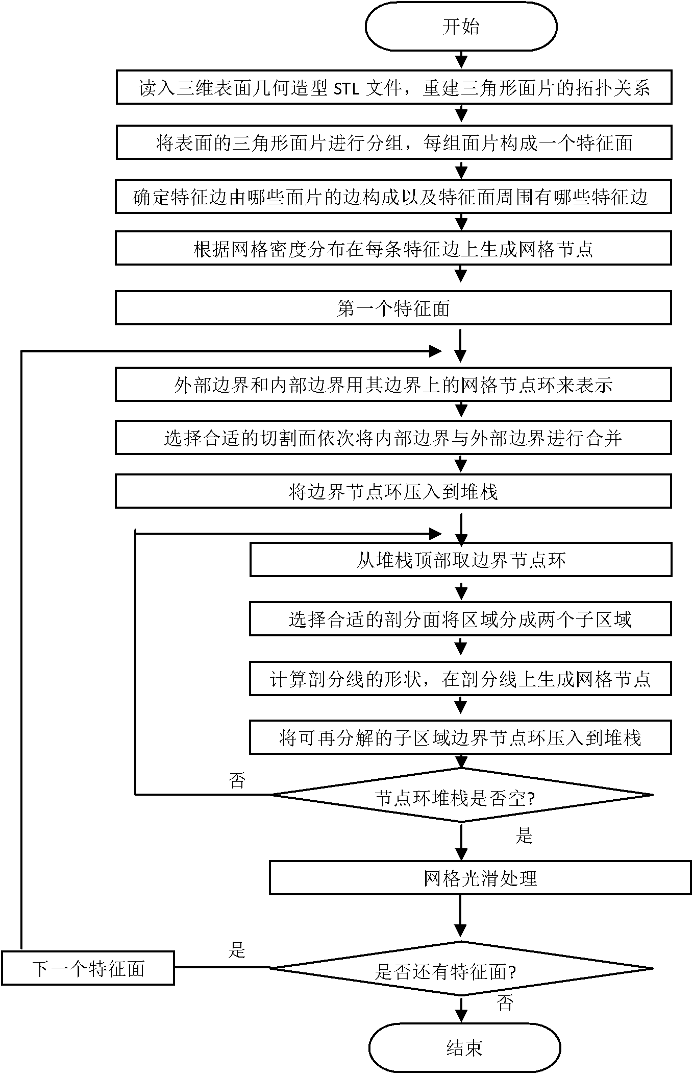
[0081] figure 1 Automatically generate flow charts for surface triangular and quadrilateral meshes of 3D solid models. according to figure 1 As shown, the process of automatically generating triangular and quadrilateral meshes on a 3D surface is as follows:

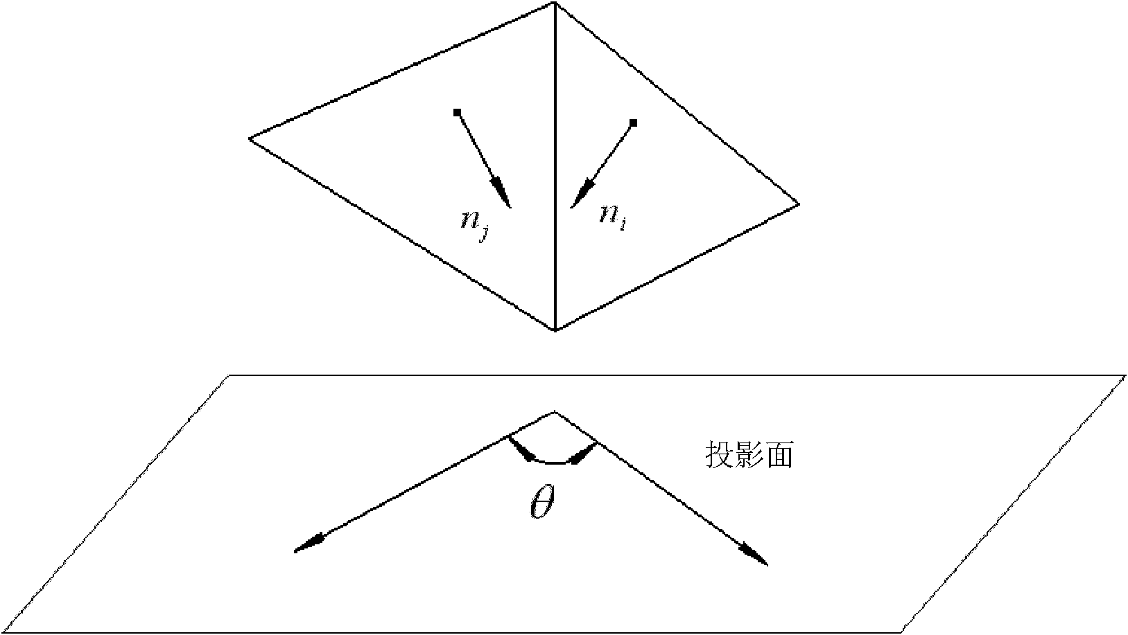
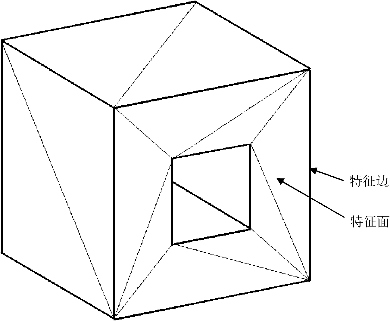
[0082] Read in the 3D surface geometric modeling STL neutral file, in which the 3D solid model or surface model is represented by a series of surface triangles, renumber the vertices of the triangles, and establish the topological relationship of the surface triangles, Including the vertex numbers of the triangle faces and the unit numbers around the triangle faces, etc., calculate the angle between adjacent faces; group the triangle faces according to the angle relationship between the faces, and each group constitutes a feature surface; Determine the surrounding boundary of each characteristic...


PUM


Abstract

The invention relates to a three-dimensional entity model surface finite element mesh automatic generation method which has the characteristics of good dimension control performance of mesh quality, density and dimension, good convergence in a dividing process, high calculation efficiency, stability and reliability. The method comprises the following steps: (1.1) establishing a three-dimensional geometrical model, reading an STL neutral file of a model surface, and reconstructing a topology relation of triangle patches; (1.2) according to a relation between a triangle patch and an adjacent patch, grouping surface triangle patches, wherein each group of triangle patches is a characteristic face; (1.3) determining boundaries of each characteristic face, and determining characteristic edges on each characteristic face boundary; (1.4) according to mesh density distribution, generating mesh nodes on each characteristic edge, and expressing boundaries of the characteristic face with mesh node rings on the boundaries; (1.5) selecting a cut surface and an optimal dissection surface, and generating mesh nodes on cut lines and dissection lines; (1.6) generating a surface mesh on each characteristic face, and carrying out smoothing process.

Description

technical field [0001] The invention belongs to the field of engineering numerical analysis, and relates to a method for automatically generating finite element grids on the surface of a three-dimensional solid model for engineering problems, and is especially suitable for limited finite element numerical analysis of engineering problems such as sheet metal stamping forming, volume forming, collision, and automobile structure. The meta-grid is automatically generated. Background technique [0002] Numerical methods such as finite element have been widely used in the analysis of various scientific and engineering problems. Before applying the finite element method for analysis, it is necessary to mesh the analysis object (that is, the solid geometric model), that is, divide the analyzed area into a limited number of units, which are connected to each other only by nodes. Mesh division is a time-consuming and error-prone process, and the quality of the mesh has a great influe...

Claims


Application Information

Patent Timeline
Patent Type & Authority Applications(China)
IPC IPC(8): G06T17/20G06F17/50
Inventor 赵国群马新武
Owner SHANDONG UNIV
Learn More