Hydraulic horizontal steel wire rope bending fatigue testing machine and annular combined gasket
A bending fatigue and steel wire rope technology, which is applied in the field of hydraulic horizontal steel wire rope bending fatigue testing machine and annular combined liner, can solve the problems of lack of test data, large inertial impact force, unsuitable for national conditions, etc., and achieve strong versatility, rigidity and The effect of high intensity and wide rotation frequency range
- Summary
- Abstract
- Description
- Claims
- Application Information
AI Technical Summary
Problems solved by technology
Method used
Image
Examples
Embodiment 1
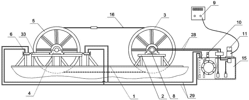
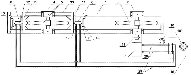
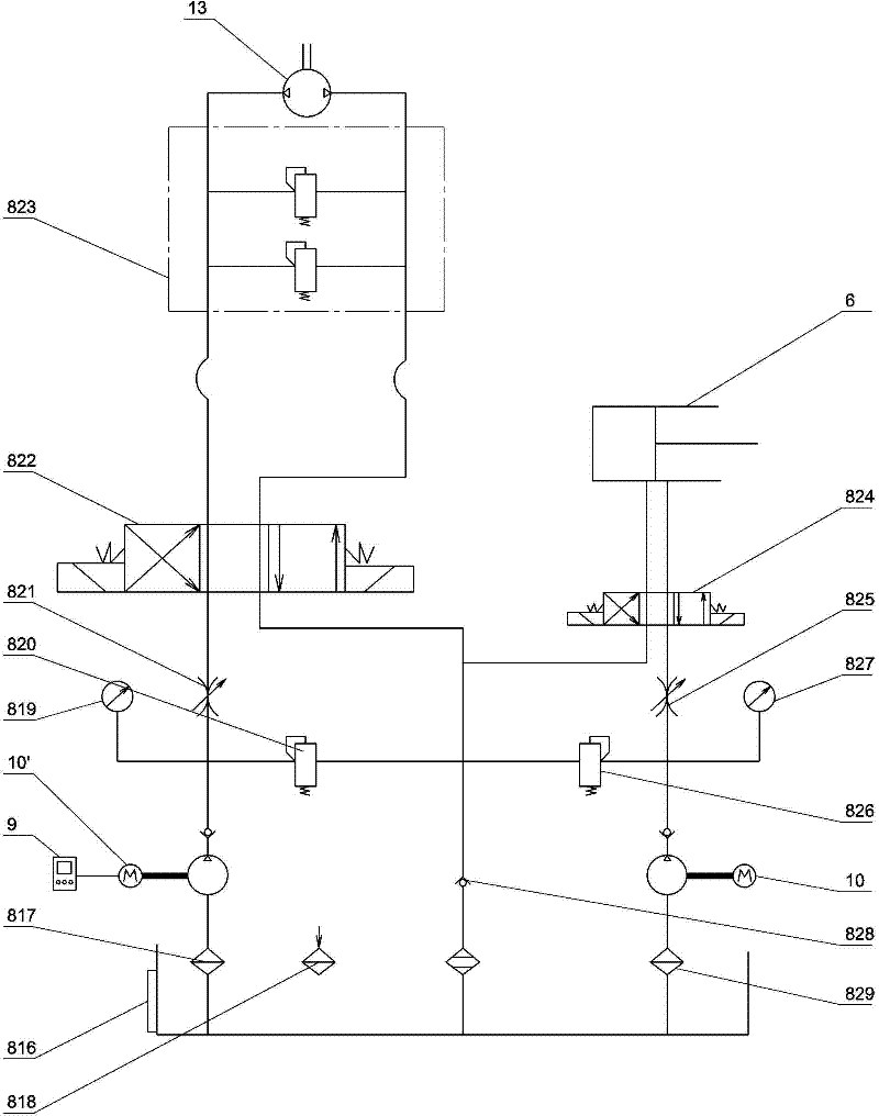
[0044] Embodiment one: see figure 1 , figure 2 , image 3 , Figure 12 and Figure 13 , a hydraulic horizontal steel wire rope bending fatigue testing machine, a rectangular foundation pit is built with concrete on the ground, a base 1 is respectively fixed around the rectangular pit groove, a bearing frame 2 is fixed at one end of the base 1, and a bearing frame is fixed 2 is equipped with a driving wheel 3, the other end of the base 1 is provided with a movable bearing frame 4 that can translate left and right, an experimental wheel 5 is installed on the movable bearing frame 4, the diameter of the driving wheel 3 is equal to that of the experimental wheel 4, and the driving wheel 3 Liners are respectively sleeved in the grooves of the test wheel and the test wheel 4. Parts of the two wheels go deep into the pit, so that the center of gravity and height of the whole testing machine are lowered, which is stable and reliable.
[0045] The bases on the left and right side...
Embodiment 2
[0052] Embodiment two: see Figure 4-Figure 9 , a ring-shaped combined liner suitable for the hydraulic horizontal steel wire rope bending fatigue testing machine described in Embodiment 1. A plurality of arc-shaped single-block liners 19 are respectively embedded in the peripheral edges of the driving wheel and the test wheel to form a ring-shaped liner .
[0053] The circumference of the driving wheel 3 and the experiment wheel 5 is provided with an annular groove 22, and at the same time, one side of the driving wheel 3 and the experiment wheel 5 is provided with an inlet 25 and a plugging 26 communicating with the groove 22. Bolts with nuts (i.e. stop bolts) are used, and each single-block liner 19 enters the annular groove from the inlet respectively to form an annular combined liner.
[0054] Flanges 24 are provided on both sides of each single-block liner 19 , and concave flanges 23 matching the flanges are provided on both side walls of the annular groove 22 of the dr...
Embodiment 3
[0057] Embodiment three: the accompanying drawings are not drawn, and the content is basically the same as that of embodiment two, and the similarities will not be repeated. The difference is that the shape of the single-block liner 19 is different, and no flange and concave edge matching structure are provided, but A retaining edge 27 is provided at the annular groove on the edge of the driving wheel or the driven wheel.
PUM
 Abstract
Description
Claims
Application Information
 - R&D
- Intellectual Property
- Life Sciences
- Materials
- Tech Scout
- Unparalleled Data Quality
- Higher Quality Content
- 60% Fewer Hallucinations
Browse by: Latest US Patents, China's latest patents, Technical Efficacy Thesaurus, Application Domain, Technology Topic, Popular Technical Reports.
© 2025 PatSnap. All rights reserved.Legal|Privacy policy|Modern Slavery Act Transparency Statement|Sitemap|About US| Contact US: help@patsnap.com


