Novel MEMS (Micro-electromechanical System) jet rotor gyroscope

A technology of jet rotor and gyroscope, applied in the field of inertial measurement, can solve problems such as low integration, and achieve the effects of ensuring accuracy, high gyro accuracy, and eliminating orthogonal coupling errors.

Inactive Publication Date: 2013-05-08
NORTHWESTERN POLYTECHNICAL UNIV
View PDF1 Cites 0 Cited by
  • Summary
  • Abstract
  • Description
  • Claims
  • Application Information

AI Technical Summary

Problems solved by technology

In the patent "jet angular velocity sensor and its preparation method" with application number 200410009349.8, it has the characteristics of impact resistance and adjustable range, and has the characteristics of unidirectional air flow, but it can only detect the angular velocity of one degree of freedom, and the integration degree is relatively low. Low

Method used


Image

  • Novel MEMS (Micro-electromechanical System) jet rotor gyroscope
  • Novel MEMS (Micro-electromechanical System) jet rotor gyroscope
  • Novel MEMS (Micro-electromechanical System) jet rotor gyroscope

Examples


Embodiment 1

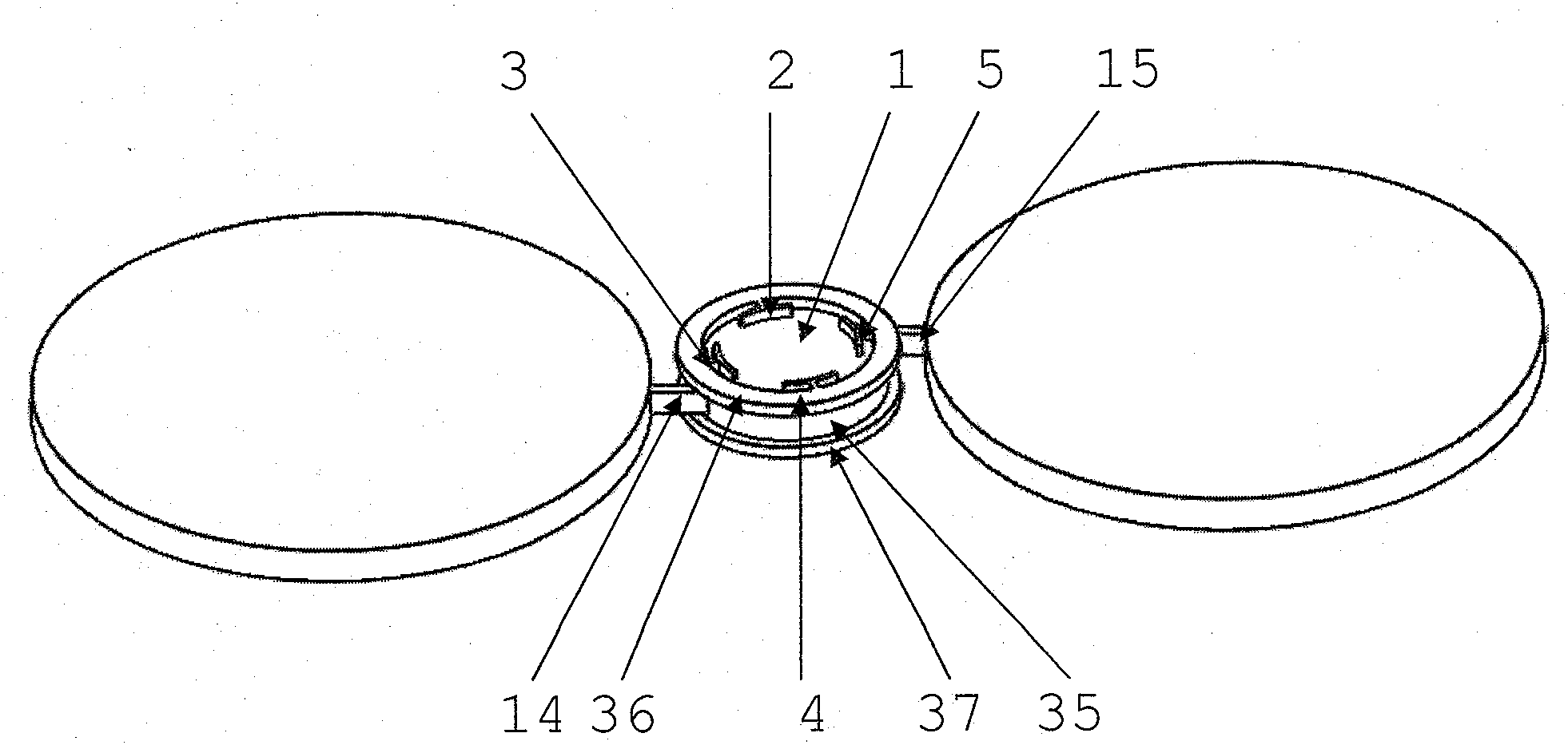
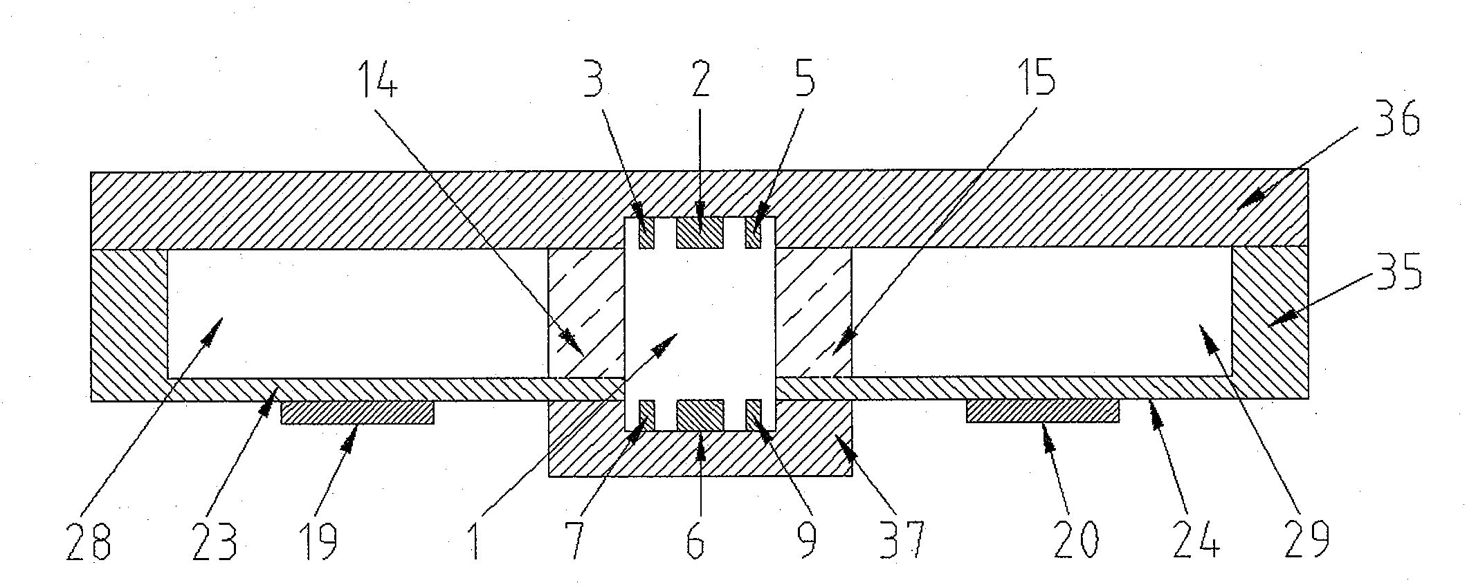
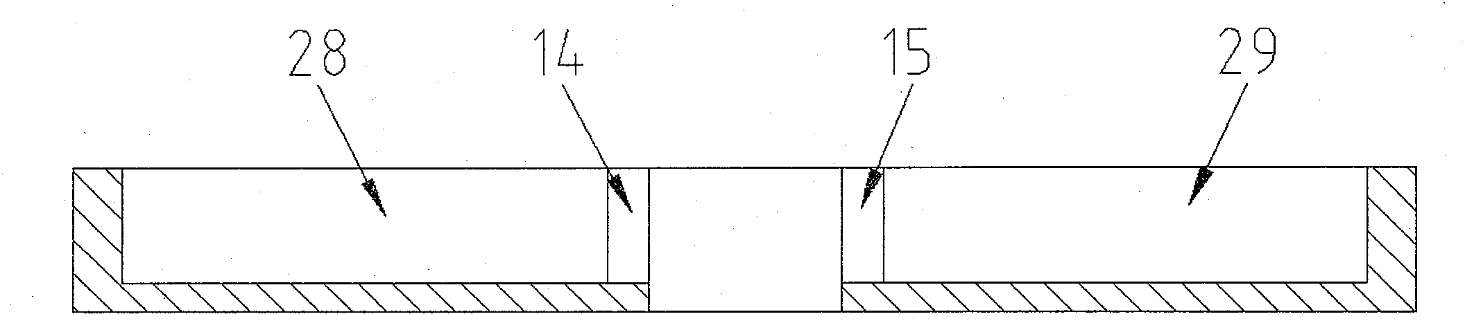
[0027] refer to figure 1 , figure 2 , image 3 , Figure 4 , Figure 5 , Figure 6 , the MEMS jet rotor gyro of the present embodiment comprises an upper detection layer 36, a cavity layer 35 and a lower detection layer 37 in turn; the cavity layer 35 has a through cylindrical cavity, which is symmetrical on both sides of the cylindrical cavity The first vibrating cavity 28 and the second vibrating cavity 29 are arranged; the first vibrating cavity 28 and the second vibrating cavity 29 do not penetrate the cavity layer 35, and the non-penetrating parts form the first vibrating film 23 and the second vibrating film respectively 24; the cylindrical cavity communicates with the first vibration chamber 28 and the second vibration chamber 29 through the first nozzle 14 and the second nozzle 15 respectively; the first nozzle 14 and the second nozzle 15 are radially staggered; the first vibration The first piezoelectric sheet 19 and the second piezoelectric sheet 20 are respect...

Embodiment 2

[0032] refer to Figure 8 and Figure 9 , the MEMS jet rotor gyroscope of the present embodiment includes an upper detection layer, a cavity layer and a lower detection layer in turn; the cavity layer has a through cylindrical cavity, and first circumferentially evenly distributed around the cylindrical cavity. The vibration cavity 28, the second vibration cavity 29, the third vibration cavity 30 and the fourth vibration cavity 31; the first vibration cavity 28, the second vibration cavity 29, the third vibration cavity 30 and the fourth vibration cavity 31 do not pass through the described Cavity layer 35, the first vibrating film, the second vibrating film, the third vibrating film and the fourth vibrating film are respectively formed in the non-penetrating part; 16. The fourth nozzle 17 communicates with the first vibration chamber 28, the second vibration chamber 29, the third vibration chamber 30 and the fourth vibration chamber 31; the first nozzle 14, the second nozzle...


PUM


Abstract

The invention discloses a novel MEMS (Micro-electromechanical System) jet rotor gyroscope, belonging to the field of inertia measurement. In the invention, a synthetic jet device enclosing a detection chamber for one circle is adopted for alternatively jetting gas so as to generate an airflow rotor. The airflow rotor has stable axis and obverse motion existing in traditional rotors; when angular speed and accelerated speed is input from the external, the airflow rotor can move when sensing the angular speed and accelerated speed, and a thermistor is used for measuring the angular speed and the accelerated speed input from the external by detecting the motion of the airflow rotor. Furthermore, the MEMS jet rotor gyroscope can be compatible with micro processing technology, and can process the detecting chamber and the vibration chamber of lateral jet type synthetic jet device simultaneously without needing complex micro assembly process; therefore, the process flow is simplified, simultaneously the accuracy of components can be ensured. In the novel MEMS jet rotor gyroscope, the advantages of MEMS rotor gyroscopes and MEMS jet rotor gyroscopes are inherited, and the shortcomings of MEMS vibration gyroscopes, the MEMS rotor gyroscopes and the MEMS jet rotor gyroscopes are abandoned; therefore, the novel MEMS jet rotor gyroscope has great research application value and wide development prospect.

Description

[0001] Field [0002] The invention proposes a novel MEMS jet rotor gyroscope technology, which belongs to the field of inertial measurement. Background technique [0003] Micro-Electro-Mechanical Systems (MEMS) is an enabling technology for the fabrication of micro-machines using silicon-based semiconductor processes. The combination of MEMS technology and gyroscope technology has produced many micro gyroscopes with new principles. It mainly includes: MEMS vibrator gyroscope (Micromachined Coriolis Vibratory Gyroscope, MCVG), MEMS rotor gyroscope (Micromachined Coriolis Rotary Gyroscope, MCRG), and MEMS jet gyroscope (Micromachined Coriolis Fluidic Gyroscope, MCFG). Due to the advantages of small size, light weight, low cost, low power consumption, and high reliability, these miniaturized gyroscopes are widely used in automotive electronics, consumer electronics, aerospace and other fields, and have become an important development direction of current inertial technology. ...

Claims


Application Information

Patent Timeline
Patent Type & Authority Patents(China)
IPC IPC(8): G01C19/02G01C19/14G01C19/42
Inventor 常洪龙谢中建李小卿杨勇丁继亮苑伟政
Owner NORTHWESTERN POLYTECHNICAL UNIV
Why Eureka
Try Eureka