Tooth belt double-shaft guide rod groove cam combination space mechanism for sliding-plug door
What is Al technical title?
Al technical title is built by PatSnap Al team. It summarizes the technical point description of the patent document.
A technology of combining space and sliding doors, applied in the direction of power control mechanism, wing fan control mechanism, door device, etc., can solve the problem of low bearing capacity, and achieve the effect of weight reduction, small size and high linear speed
Inactive Publication Date: 2014-04-02
NANJING INST OF TECH
View PDF6 Cites 2 Cited by
Summary
Abstract
Description
Claims
Application Information
AI Technical Summary
This helps you quickly interpret patents by identifying the three key elements:
Problems solved by technology
Method used
Benefits of technology
Problems solved by technology
[0011] In recent years, toothed belt transmission has been greatly improved in terms of material and structure. For example, neoprene toothed belt adopts glass fiber tensile layer, neoprene toothed belt, belt back and nylon cloth layer, polyurethane polyester tensile toothed belt etc. Combining the advantages of gear, chain and belt transmission, it overcomes the shortcomings of traditional toothed belt transmission, such as extension, fragility, and low load-bearing capacity, and has the advantages of accurate transmission, low noise, high load-bearing capacity, long life, high reliability, and energy saving. High efficiency, small pre-tightening force, etc.
Method used
Image
Click on the blue label to locate the original text in one second.
Reading with bidirectional positioning of images and text.
Examples
Embodiment Construction
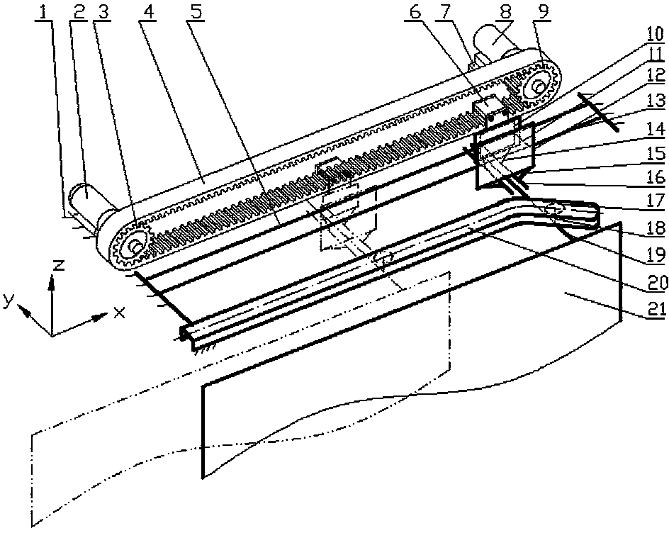
[0032] Refer to attached Figure 1~4 , a slotted cam combined space mechanism with double-axis guide rods in a plug door tooth belt, including a door frame 1, a motor 2, a driving wheel 3, a toothed belt 4, an auxiliary bearing shaft 5, a lower belt clamp 6, a tensioning device 7, and a bearing seat 8. Driven wheel 9, auxiliary shaft sleeve 10, connecting rod A 11, main shaft sleeve 12, main bearing shaft 13, connecting rod B14, connecting rod C15, guide rod sleeve 16, roller 17, roller shaft 18, door guide Rod 19, grooved cam 20 and door leaf 21; wherein driving wheel 3, toothed belt 4, lower belt clip 6, tensioning device 7, bearing seat 8, driven wheel 9 form a toothed belt transmission mechanism; link A 11, main shaft Sleeve 12, connecting rod B14, connecting rod C15, and guide rod sleeve 16 are consolidated into one body, forming a biaxial guide rod mechanism with main shaft 13, auxiliary bearing shaft 5, door frame 1, etc.; main shaft sleeve 12, main shaft 13, and connecti...
PUM
Abstract
The invention discloses a tooth belt double-shaft guide rod groove cam combination space mechanism for a sliding-plug door, relates to a sliding and plug, sealing, opening and closing mechanism for the sliding-plug door for a vehicle, in particular to the tooth belt double-shaft guide rod groove cam combination space mechanism for high-speed rail or other railway vehicles. The mechanism comprises a door frame, a motor, a driving wheel, a tooth belt, an auxiliary bearing shaft, a belt clamp, a tension device, a bearing pedestal, a driven wheel, an auxiliary shaft sleeve, a coupling rod A, a main shaft sleeve, a main bearing shaft, a coupling shaft B, a coupling shaft C, a guide rod sleeve, a roller, a roller shaft, a door carrying guide rod, a groove cam and a door leaf; a tooth belt transmission mechanism consists of the driving wheel, the tooth belt, a lower belt clamp, the tension device, the bearing pedestal, and the driven wheel; a double-shaft guide rod mechanism consists of the coupling rod A, the main shaft sleeve, the coupling rod B, the coupling rod C and the guide rod sleeve which are connected fixedly and integrally, the main bearing shaft, the auxiliary shaft, and the door frame; and a groove cam mechanism consists of the main shaft sleeve, the main shaft, the coupling rod C, the roller, the roller shaft, the door carrying guide rod, the groove cam, the door leaf, the main shaft sleeve and the door frame.
Description
technical field [0001] The present invention relates to a slotted cam combination space mechanism of a plug door with biaxial guide rod and relates to a plug sealing opening and closing mechanism of a vehicle plug door, in particular to a high-speed rail or other rail vehicle plug door with biaxial Guide rod slot cam combined space mechanism. Background technique [0002] At present, the automatic doors of rail vehicles at home and abroad mainly include three series of door systems: plug doors, external doors and built-in doors. The transmission methods mainly include screw transmission and toothed belt (ie synchronous toothed belt) transmission. [0003] The sliding door system is usually a single or double door leaf. When it is a double leaf, on the one hand, it needs to realize the opening and closing movement of the two door leaves that are opened and closed. The door leaf plug moves inward to ensure a good sealing effect after closing the door. Screw drive means that ...
Claims
Application Information
Patent Timeline
Application Date:The date an application was filed.
Publication Date:The date a patent or application was officially published.
First Publication Date:The earliest publication date of a patent with the same application number.
Issue Date:Publication date of the patent grant document.
PCT Entry Date:The Entry date of PCT National Phase.
Estimated Expiry Date:The statutory expiry date of a patent right according to the Patent Law, and it is the longest term of protection that the patent right can achieve without the termination of the patent right due to other reasons(Term extension factor has been taken into account ).
Invalid Date:Actual expiry date is based on effective date or publication date of legal transaction data of invalid patent.