


Quick Research
Generate reliable direction feasibility study reports for your R&D in just a few steps.

Technical Q&A
Discover and master advanced knowledge NOW. Basics, ideas, possibilities, all at once.

Find Solutions
As an expert in R&D theories, this can generate solutions to your technical problems instantly.

Evaluate Feasibility
Analyze your overall solution with one click, know your potential R&D risks in advance.

Monitor Landscape
Get weekly tech updates, stay abreast of the latest tech innovations and key insights.
Clamp for sticky side sticker of non-ferrous metal electrolytic cathode board
A technology for electrolyzing cathode plates and non-ferrous metals, which is applied in the direction of electrodes, electrolysis process, electrolysis components, etc., can solve the problems of easy production accidents, inconvenient production management, and high pasting costs, so as to facilitate production management, improve automation level, reduce The effect of production costs
- Summary
- Abstract
- Description
- Claims
- Application Information
AI Technical Summary
Problems solved by technology
Method used
Image

Examples
Embodiment 1
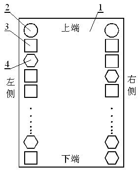
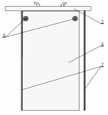
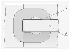
[0014] Embodiment 1: see Figure 1-3 , the non-ferrous metal electrolysis cathode plate adhesive edge sticking fixture is composed of a clamp body 1 and a rubber strip pressure-holding mechanism 4, the structure shape of the clamp body 1 is consistent with the shape of the electrolysis cathode plate, and its left and right sides are from top to bottom Two (one on each side) adhesive strip pressure-holding mechanisms 4 are provided. The clamp body 1 is an integral cast steel structural part, and its size is 1000 mm long x 600 mm wide x 100 mm high. The rubber strip pressure maintaining mechanism 4 realizes the clamping and pressure maintaining of the rubber strip through the gravitational potential energy of the weight, and realizes the release of the rubber strip pressure maintaining mechanism 4 through electric (motor) driving. Because there is no mechanism for advancing and embedding the rubber strip, it is necessary to push and embed the rubber strip on the cathode plate b...
Embodiment 2
[0015] Example 2: see Figure 1-3 , the non-ferrous metal electrolysis cathode plate adhesive edge sticking fixture is composed of a clamp body 1 and a rubber strip pressure-holding mechanism 4, the structure shape of the clamp body 1 is consistent with the shape of the electrolysis cathode plate, and its left and right sides are from top to bottom There are 10 (5 on each side) rubber strip pressure maintaining mechanisms 4 evenly arranged. The clamp body 1 is an integral cast iron structural part, and its size is 1600 mm x 850 mm wide x 180 mm high. The rubber strip pressure maintaining mechanism 4 realizes the clamping and pressure maintaining of the rubber strip through a spring, and realizes the release of the rubber strip pressure maintaining mechanism 4 through a pneumatic (cylinder) driving mode. The uppermost end of the left and right sides of the clamp body 1 is provided with an electrolytic nonferrous metal stripping port injection pressure holding mechanism 2, and ...
Embodiment 3
[0016] Embodiment 3: see Figure 1-3 , the non-ferrous metal electrolysis cathode plate adhesive edge sticking fixture is composed of a clamp body 1 and a rubber strip pressure-holding mechanism 4, the structure shape of the clamp body 1 is consistent with the shape of the electrolysis cathode plate, and its left and right sides are from top to bottom There are 30 (15 on each side) adhesive strip pressure-holding mechanisms 4 evenly interlaced. The clamp body 1 is an integral cast iron structural part, and its size is 1800mm×width 1100mm×height 200mm. The rubber strip pressure maintaining mechanism 4 realizes the clamping and pressure maintaining of the rubber strip through the elastic potential energy of the spring, and realizes the release of the rubber strip pressure maintaining mechanism 4 through the hydraulic (hydraulic cylinder) driving mode. The uppermost end of the left and right sides of the clamp body 1 is provided with an injection molding pressure-holding mechani...
PUM
 Abstract
Description
Claims
Application Information
 - R&D Engineer
- R&D Manager
- IP Professional
- Industry Leading Data Capabilities
- Powerful AI technology
- Patent DNA Extraction
Browse by: Latest US Patents, China's latest patents, Technical Efficacy Thesaurus, Application Domain, Technology Topic, Popular Technical Reports.
© 2024 PatSnap. All rights reserved.Legal|Privacy policy|Modern Slavery Act Transparency Statement|Sitemap|About US| Contact US: help@patsnap.com