An electron beam welding method for an ultra-supercritical partition
An electron beam welding and ultra-supercritical technology, which is applied in the field of steam turbines, can solve the problems of difficulty in ensuring welding quality, difficulty in welding seam cleaning, and difficulty in welding seam forming, and achieves the advantages of less difficulty in welding, reducing the probability of repairing, and improving welding quality. Effect
- Summary
- Abstract
- Description
- Claims
- Application Information
AI Technical Summary
Problems solved by technology
Method used
Image

Examples
specific Embodiment approach 1
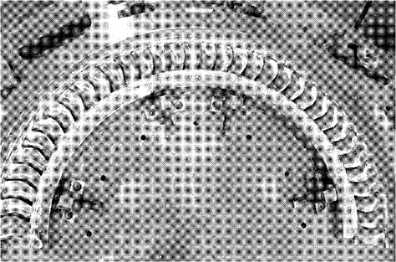
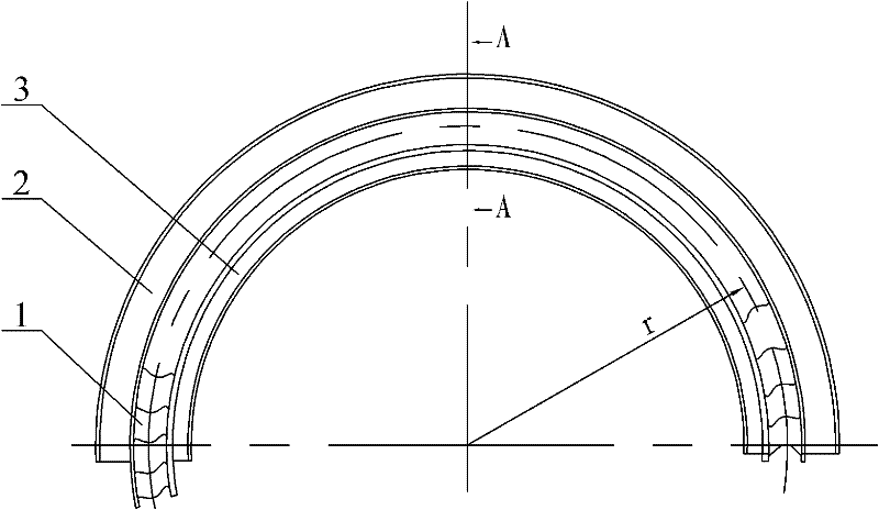
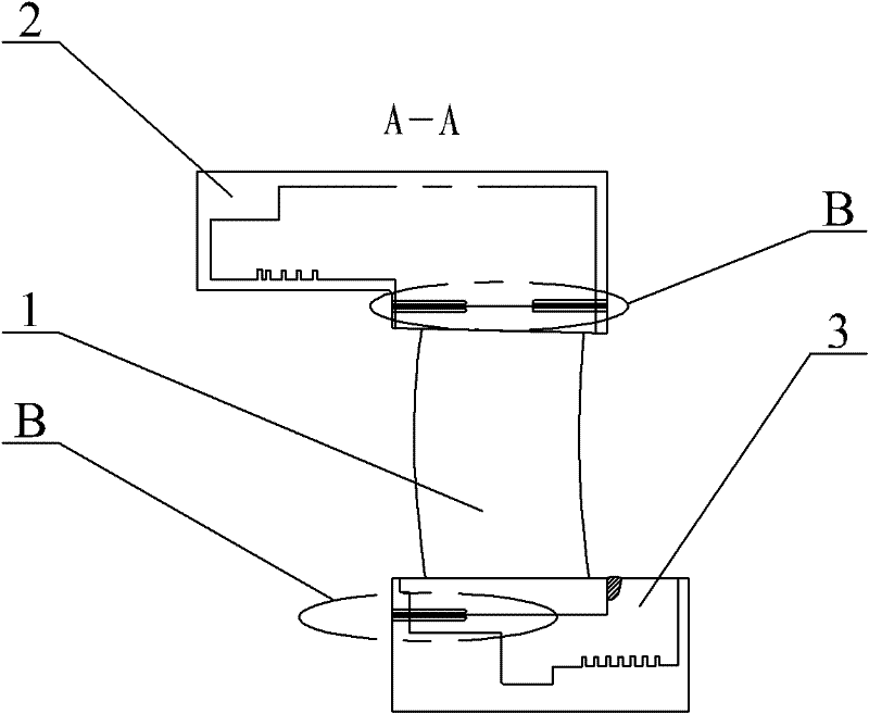
[0018] Specific implementation mode one: combine Figure 1 ~ Figure 3 Illustrate, a kind of electron beam welding method of ultra-supercritical separator of the present embodiment, described method is realized according to the following steps:
[0019] Step 1. Marking: draw the horizontal mid-section line on the inner plate body 3, the outer plate body 2 and the tooling (according to the design requirements), and draw the horizontal mid-section line on the first guide vane and the end guide vane (The scribe line should be clear) and make a hole in the corresponding position for observation (the corresponding position refers to the drawn horizontal mid-plane line, punch the hole on the line, so that the trace is clear and easy to observe during electron beam welding, otherwise the scribe line not visible while in the welder);
[0020] Step 2. Assembly: According to the line drawn in step 1, assemble the outer plate body 2 on the tooling, and use the outer plate body 2 as the p...
specific Embodiment approach 2
[0035] Specific embodiment two: in step six of the present embodiment, the accelerating voltage during preheating is 55KV, the welding speed is 800mm / min, the electron beam current is 50mA, the focusing current is 1550mA, and the scanning swing of the electron beam in the X direction is 0, the scanning swing of the electron beam in the Y direction is 0, and the gun distance is 320mm;
[0036]The accelerating voltage during sealing welding is 55KV, the welding speed is 250mm / min, the electron beam current is 85mA, the focusing current is 1850mA, the scanning swing of the electron beam in the X direction is 0, and the scanning swing of the electron beam in the Y direction is 0 , the gun distance is 320mm;
[0037] The accelerating voltage during welding is 55KV, the welding speed is 250mm / min, the electron beam current is 210mA, the focusing current is 1850mA, the scanning swing of the electron beam in the X direction is 0, and the scanning swing of the electron beam in the Y di...
specific Embodiment approach 3
[0040] Specific embodiment three: the accelerating voltage during the preheating in step six of the present embodiment is 55KV, welding speed is 400mm / min, electron beam current is 80mA, focusing current is 1550mA, and the scanning swing of electron beam in X direction is 0, the scanning swing of the electron beam in the Y direction is 0, and the gun distance is 320mm;
[0041] The accelerating voltage during sealing welding is 55KV, the welding speed is 300mm / min, the electron beam current is 85mA, the focusing current is 1850mA, the scanning swing of the electron beam in the X direction is 0, and the scanning swing of the electron beam in the Y direction is 0 , the gun distance is 320mm;
[0042] The accelerating voltage during welding is 55KV, the welding speed is 250mm / min, the electron beam current is 210mA, the focusing current is 1850mA, the scanning swing of the electron beam in the X direction is 0, and the scanning swing of the electron beam in the Y direction is 0. ...
PUM
| Property | Measurement | Unit |
|---|---|---|
| Length | aaaaa | aaaaa |
Abstract
Description
Claims
Application Information
 - R&D
- Intellectual Property
- Life Sciences
- Materials
- Tech Scout
- Unparalleled Data Quality
- Higher Quality Content
- 60% Fewer Hallucinations
Browse by: Latest US Patents, China's latest patents, Technical Efficacy Thesaurus, Application Domain, Technology Topic, Popular Technical Reports.
© 2025 PatSnap. All rights reserved.Legal|Privacy policy|Modern Slavery Act Transparency Statement|Sitemap|About US| Contact US: help@patsnap.com