
A voltage equalizing circuit and a voltage equalizing method for a DC capacitor voltage of a multilevel converter

A DC capacitor and voltage equalizing circuit technology, applied in the direction of converting AC power input to DC power output, electrical components, output power conversion devices, etc., can solve problems such as loss and affecting the safety of the converter itself, and achieve simple strategies and production Low maintenance cost and wide application range

Active Publication Date: 2011-12-21
成都拓及兴通科技有限公司
View PDF5 Cites 3 Cited by
  • Summary
  • Abstract
  • Description
  • Claims
  • Application Information

AI Technical Summary

Problems solved by technology

When the multilevel converter transmits pure active current, that is, when the load current angle is near 0 degrees, in order to ensure the stability of the DC voltage, the PWM modulation depth is required to be the highest and less than about 55%, which greatly limits the active power of the diode clamp circuit. Applications in the field of delivery
After the DC voltage is unstable, the multi-level converter will degenerate into a two-level converter, and at the same time lose many advantages of multi-level, and even affect the safety of the converter itself

Method used


Image

  • A voltage equalizing circuit and a voltage equalizing method for a DC capacitor voltage of a multilevel converter
  • A voltage equalizing circuit and a voltage equalizing method for a DC capacitor voltage of a multilevel converter
  • A voltage equalizing circuit and a voltage equalizing method for a DC capacitor voltage of a multilevel converter

Examples


specific Embodiment approach

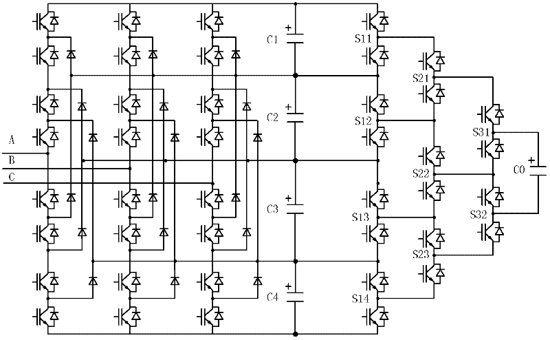
[0022] figure 2 It is shown that a specific embodiment of the present invention is: a voltage equalization circuit for a DC capacitor voltage of a five-level converter, which is used for equalizing the DC capacitor voltage of a diode-clamped five-level converter. The composition of the voltage equalizing circuit is: 4 DC capacitors C1, C2, C3, and C4 on the DC side of the diode-clamped multilevel converter are connected with the voltage equalizing switch array composed of a plurality of auxiliary switching devices. The corresponding input terminals are connected, the output terminal of the voltage equalizing switch array is connected with an auxiliary DC capacitor C0, and the control terminal of each auxiliary switching device in the voltage equalizing switch array is connected with the control device of the multilevel converter.

[0023] The specific composition of the voltage equalizing switch array in this example is:

[0024] Two auxiliary switching devices are connected...

Embodiment 2

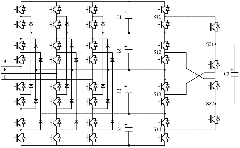
[0038] image 3 It shows that this example is the same as the first embodiment, and it is also a voltage equalization circuit for the DC capacitor voltage of the five-level converter, which is used for equalizing the DC capacitor voltage of the diode-clamped five-level converter. Its composition is also: the four DC capacitors C1, C2, C3, and C4 on the DC side of the diode-clamped multilevel converter are all connected to the corresponding input terminals of the voltage equalizing switch array composed of multiple auxiliary switching devices, The output end of the voltage equalizing switch array is connected to an auxiliary DC capacitor C0, and the control end of each auxiliary switching device in the voltage equalizing switch array is connected to the control device of the multilevel converter.

[0039] The voltage equalizing switch array of this example is different from Embodiment 1, and the specific composition of its voltage equalizing switch array is: the midpoints of th...


PUM


Abstract

The invention discloses a voltage equalization circuit and a voltage equalization method for DC capacitors of a multi-level converter. The voltage equalization circuit is formed in a way that: N DC capacitors Cn on the DC side of a diode-clamped multi-level converter are all connected with the corresponding input ends of a voltage equalizing switch array consisting of a plurality of auxiliary switching devices; n is one of 1, 2, ..., N; the output end of the voltage equalizing switch array is connected with an auxiliary DC capacitor (C0); the control end of each auxiliary switching device in the voltage equalizing switch array is connected with a control device of the multi-level converter; and N is a difference obtained by subtracting 1 from a level number of the multi-level converter. The circuit can realize the voltage equalization and stabilization of the DC capacitors under any power factor condition, particularly in the transmission of active current to free the PWM depth of the converter from the restrictions of DC voltage stabilization conditions and ensure the realization of active or reactive transmission under any modulation depth condition, and has a simple structure, low cost and high reliability.

Description

technical field [0001] The invention relates to a voltage equalizing circuit and a voltage equalizing method for a DC capacitor voltage of a multilevel converter. Background technique [0002] The diode-clamped multilevel converter uses multiple series-connected DC capacitors connected to both ends of the DC side. At the same time, multiple series-connected switching devices of each bridge arm of the converter are connected to each DC capacitor through a diode, that is, through a diode Clamp the voltage of the switching device to a DC capacitor voltage connected to divide the DC bus voltage into multiple levels. Therefore, the multiple switching devices of each bridge arm can output voltage signals of different levels to the AC side under different switch combinations. Through various PWM (Pulse Width Modulation, pulse width modulation) modulation methods, the diode-clamped multilevel converter synthesizes multiple level output signals into modulation signals. The more leve...

Claims


Application Information

Patent Timeline
Patent Type & Authority Applications(China)
IPC IPC(8): H02M7/487
Inventor 舒泽亮
Owner 成都拓及兴通科技有限公司
Learn More