Arc striking device for electric switch equipment

An arc striking device, electric switch technology, applied in electric switches, high-voltage/high-current switches, circuits, etc., can solve the problem of contact burnout, require high contact resistance to burnout, affect the reliability of switch operation and service life and other issues, to achieve the effect of reducing the degree of burning loss, shortening the burning time, and improving the service life

Active Publication Date: 2015-04-22
CHINA XD ELECTRIC CO LTD +1
View PDF7 Cites 0 Cited by
  • Summary
  • Abstract
  • Description
  • Claims
  • Application Information

AI Technical Summary

Problems solved by technology

[0003] The traditional switch structure has only one pair of arcing contacts. During the process of breaking the fault current, the arc will always burn between the moving and static contacts until the arc is extinguished. This kind of working condition requires high resistance to burning of the contacts, especially for high-current breaking. The burning of the contacts is more serious, which directly affects the operational reliability and service life of the switch

Method used


Image

  • Arc striking device for electric switch equipment
  • Arc striking device for electric switch equipment
  • Arc striking device for electric switch equipment

Examples


Embodiment Construction

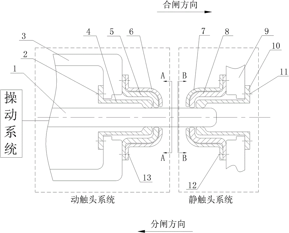
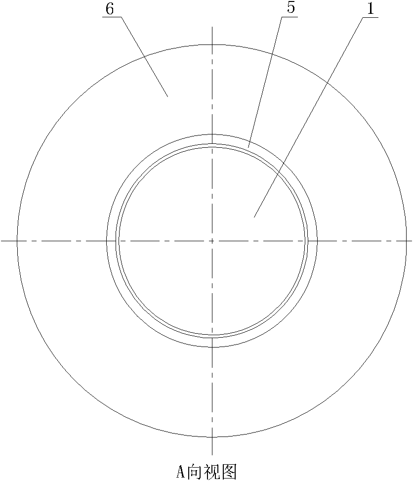
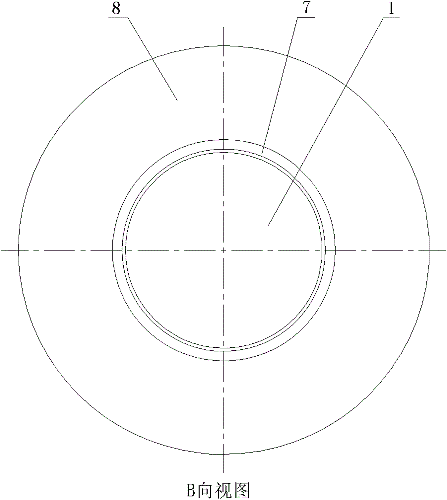
[0016] see Figure 1 to Figure 3 As shown, the arc striking device provided by the present invention is composed of two parts: a moving contact system and a static contact system. 5 and the moving side insulation cover 6, the static contact system includes the static side insulation cover 7, the static side arc ring 8, the conductive support 9 and the static arc contact 10.

[0017] The auxiliary contact 4 is fixed on the contact finger seat 3 with the screw 2, and the moving arc contact 1 moves left and right along the axial direction under the drive of the operating system to complete the opening and closing operation. The moving arc contact 1 slides on the auxiliary contact 4, and the two maintain reliable electrical contact. The moving arc contact 1, the auxiliary contact 4 and the contact finger seat 3 form a conductive channel. The moving side arc ring 5 and the moving side insulating cover 6 are fixed on the contact finger seat 3 with screws 13, and they cover the auxi...


PUM


Abstract

The invention provides an arc striking device for electric switch equipment. The arc striking device comprises a moving contact system and a fixed contact system; the moving contact system comprises a moving arc contact, a contact finger seat, and an auxiliary contact, a moving arc striking ring and a moving insulating cover which are sequentially fixed on the contact finger seat in the switch-on direction; the fixed contact system comprises a conductive support piece, and a static insulating cover, a static arc striking ring and a static arc contact which are sequentially fixed on the conductive support piece in the switch-on direction; and when the arc striking device is in a switch-on state, the moving arc contact passes through openings of the auxiliary contact, the moving arc striking ring, the moving insulating cover, the static insulating cover, the static arc striking ring and the static arc contact, and is electrically contacted with the auxiliary contact and the static arc contact. Since the moving arc striking ring and the static arc striking ring are arranged outside the moving arc contact and the static arc contact, the burning time of arc on the arc contacts when the switch cuts off fault current is shortened, the burning degree of the contacts is reduced, the contact reliability of the contacts is ensured, and the service life of the switch is prolonged.

Description

technical field [0001] The invention relates to an arc striking device for a gas-insulated high-voltage switch. Background technique [0002] When the switch breaks the fault current, the main contacts are separated first, and the fault current is borne by the arcing contacts. When the moving and static arcing contacts are separated, high-temperature arcs appear between the contacts. The erosion will become more and more serious, and the situation will not be terminated until the fault current is completely interrupted. [0003] The traditional switch structure has only one pair of arcing contacts. During the process of breaking the fault current, the arc will always burn between the moving and static contacts until the arc is extinguished. This kind of working condition requires high resistance to burning of the contacts, especially for high-current breaking. The burning situation of the contact is more serious, which directly affects the operational reliability and servic...

Claims


Application Information

Patent Timeline
Patent Type & Authority Patents(China)
IPC IPC(8): H01H33/04
Inventor 程立马曾锐吕军玲徐刚雷肖
Owner CHINA XD ELECTRIC CO LTD
Why Eureka
Try Eureka