
Winding device and winding method for a shim superconducting coil

A technology of superconducting coil and superconducting wire, which is applied in superconducting magnet/coil, coil manufacturing, inductor/transformer/magnet manufacturing and other directions, can solve the problems of cumbersome operation process and complicated winding device, and achieves low cost and simple method. , the effect of simple installation

Active Publication Date: 2011-12-21
INST OF ELECTRICAL ENG CHINESE ACAD OF SCI
View PDF8 Cites 17 Cited by
  • Summary
  • Abstract
  • Description
  • Claims
  • Application Information

AI Technical Summary

Problems solved by technology

[0006] The purpose of the present invention is to overcome the shortcomings of the existing winding device complex and cumbersome operation process, and provide a device and winding method for winding shim superconducting coils

Method used


Image

  • Winding device and winding method for a shim superconducting coil
  • Winding device and winding method for a shim superconducting coil
  • Winding device and winding method for a shim superconducting coil

Examples


Embodiment Construction

[0019] The present invention will be further described below in conjunction with the accompanying drawings and specific embodiments.

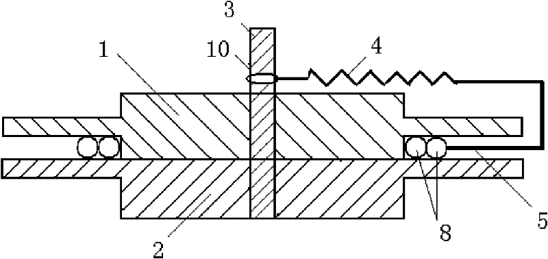
[0020] Such as figure 1 As shown, the device of the present invention includes an upper cover plate 1 , a lower cover plate 2 , a central column 3 , a spring 4 , a pressure needle 5 , a fixing fixture 6 , a screw 9 , and a ring 10 . Both the upper cover 1 and the lower cover 2 are in the shape of a plane runway. The upper cover 1 and the lower cover 2 are connected together by 3 columns in the center. The upper cover 1 and the lower cover 2 have rectangular teeth around the edges. The upper cover There is a gap equal to the diameter of the superconducting wire between the rectangular teeth of the plate 1 and the lower cover plate 2 . The superconducting wires 8 have relatively high elasticity when bent, and if they are not restrained, the arrangement of the superconducting wires will not be tight. The ring 10 is set on the central column 3, t...


PUM


Abstract

The invention relates to a winding device for a shimming superconducting coil, which comprises an upper cover plate (1), a lower cover plate (2), a central column (3), a spring (4), a pressure needle (5), a fixing clamp (6), a superconducting wire (8), a screw (9) and a ring (10). The upper cover plate (1) and the lower cover plate (2) are connected through the central column (3), and a clearancewith the size identical to the diameter of the wire is left between rectangular teeth of the upper cover plate (1) and the lower cover plate (2). The superconducting wire (8) pressed by the top end of the pressure needle (5) with the spring mechanism (4) slides along the circumference on a horizontal plane to be wound the superconducting coil.

Description

technical field [0001] The invention relates to a winding device and method of a superconducting coil, in particular to a winding device and a winding method of a superconducting coil for compensating the uniformity of a magnetic field. Background technique [0002] Compared with traditional medical imaging equipment such as X-rays, CT scanners, and ultrasonic imagers, MRI (Magnetic Resonance Imaging, MRI) systems have many imaging parameters, rich diagnostic information, high image resolution, and can be sliced ​​in any direction and wirelessly. With the advantages of ionizing radiation and other advantages, it has become the most advanced medical imaging equipment at present. The magnet is the core component used to provide the background magnetic field of the MRI system. The magnetic field strength is one of the important indicators of the MRI system, and it is directly proportional to the image signal-to-noise ratio. An MRI system with a high magnetic field strength can...

Claims


Application Information

Patent Timeline
IPC IPC(8): H01F6/06H01F41/06H01F41/064H01F41/082
Inventor 胡新宁王秋良文聪倪志鹏宋守森
Owner INST OF ELECTRICAL ENG CHINESE ACAD OF SCI
Learn More