


Quick Research
Generate reliable direction feasibility study reports for your R&D in just a few steps.

Technical Q&A
Discover and master advanced knowledge NOW. Basics, ideas, possibilities, all at once.

Find Solutions
As an expert in R&D theories, this can generate solutions to your technical problems instantly.

Evaluate Feasibility
Analyze your overall solution with one click, know your potential R&D risks in advance.

Monitor Landscape
Get weekly tech updates, stay abreast of the latest tech innovations and key insights.
A Method for Identifying Internal and External Faults of DC Transmission Line Based on Performance Equation of Smoothing Inductive Components
A technology of direct current transmission lines and inductive components, which is applied in the direction of the fault location, etc., can solve the problems of poor setting of setting values, non-repeatable limitations, and difficulty in capturing traveling wave signals, etc., and achieve excellent reliability and sensitivity of the action, Accelerates the effect of backup protection
- Summary
- Abstract
- Description
- Claims
- Application Information
AI Technical Summary
Problems solved by technology
Method used
Image


Examples
Embodiment 1
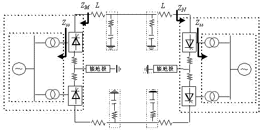
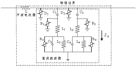
[0029] Example 1: ±800kV DC transmission line (transmission system structure such as figure 1 ). The transmission capacity is 5000MW, and the reactive power compensation capacity on the rectifier side and the inverter side is 3000Mvar and 3040Mvar; each pole commutation unit is composed of two 12-pulse converters; the DC line side is equipped with a 400mH smoothing reactor; DC The filter is a 12 / 24 / 36 three-tuned filter; the line is a six-split wire, using the J.Marti frequency line model, the line length is 1500km, and the physical boundary of the DC is as figure 1 (b), where, L =400mH, L 1 =39.09mH, L 2 =26.06mH, L 3 =19.545mH, L 4 =34.75mH, C 1 =0.9μF, C 2 =0.9μF, C 3 =1.8μF, C 4 =0.675μF.
[0030] The ground fault of the positive pole of the DC transmission line is 100km from the M terminal, the transition resistance is 10Ω, the time window length is 3ms, and the sampling frequency is 10kHz.
[0031] (1) After the DC line fails, the starting element is started, according to t...
Embodiment 2
[0034] Example 2: The DC transmission line system is the same as Example 1. The smoothing reactor outlet on the rectifier side and the inverter side of the DC line fails at the same time, the transition resistance is 10Ω, the time window length is 3ms, and the sampling frequency is 10kHz.
[0035] After the DC line fails, calculate the analog voltage waveform in the same way as in Example 1. , And its correlation coefficient with the measured voltage waveform to get =- 0.367 =-0.245 <0, judged as a fault outside the area on both sides.
Embodiment 3
[0036] Example 3: The DC transmission line system is the same as Example 1. AC system A phase ground fault (A-G) on the rectifier side of the DC line, the transition resistance is 10Ω, the time window length is 3ms, and the sampling frequency is 10kHz.
[0037] After the DC line fails, calculate the analog voltage waveform in the same way as in Example 1. , And its correlation coefficient with the measured voltage waveform to get =- 0.1842 =0.9657﹥0, judged as a fault outside the M-side zone.
[0038] The principle of the present invention is:
[0039] 1. Short window description of the fault characteristics inside and outside the DC line
[0040] (1) Fault in the DC line area
[0041] Assuming that the positive line has an area fault, the additional network of the fault component is as Figure 4 Shown. In the figure, ( Z c , γ ) Is expressed as a distributed parameter transmission line, measuring current i M , i N It uses the pole bus differential protection to measure the curre...
PUM
 Abstract
Description
Claims
Application Information
 - R&D Engineer
- R&D Manager
- IP Professional
- Industry Leading Data Capabilities
- Powerful AI technology
- Patent DNA Extraction
Browse by: Latest US Patents, China's latest patents, Technical Efficacy Thesaurus, Application Domain, Technology Topic, Popular Technical Reports.
© 2024 PatSnap. All rights reserved.Legal|Privacy policy|Modern Slavery Act Transparency Statement|Sitemap|About US| Contact US: help@patsnap.com