Method for identifying DC transmission line area inside/outside failure in simulation after test

A technology of direct current transmission lines and direct current transmission lines, applied in the direction of measuring electricity, measuring electrical variables, measuring devices, etc., can solve problems such as poor setting of setting values, non-repeatable limitations, and reliability dependence of criteria, etc., to achieve action Excellent reliability and sensitivity, accelerating the effect of backup protection

Active Publication Date: 2015-01-28
KUNMING UNIV OF SCI & TECH
View PDF1 Cites 0 Cited by
  • Summary
  • Abstract
  • Description
  • Claims
  • Application Information

AI Technical Summary

Problems solved by technology

However, since the reliability of the criterion depends on the physical boundary frequency characteristics, there will be a problem that the setting value is not easy to set in practical applications.
The DC traveling wave protection composed of the polarity of the traveling wave head can correctly identify faults inside and outside the zone, but the reliability of the traveling wave protection is limited due to the difficulty of capturing and non-repeatability of the traveling wave signal

Method used


Image

  • Method for identifying DC transmission line area inside/outside failure in simulation after test
  • Method for identifying DC transmission line area inside/outside failure in simulation after test
  • Method for identifying DC transmission line area inside/outside failure in simulation after test

Examples


Embodiment 1

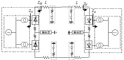
[0029] Example 1: ±800kV DC transmission line (transmission system structure such as figure 1 ). The power transmission capacity is 5000MW, and the reactive power compensation capacity of rectification side and inverter side is 3000Mvar and 3040Mvar; each pole commutation unit is composed of two 12-pulse converters; DC line side is equipped with 400mH smoothing reactor; DC The filter is a 12 / 24 / 36 three-tuned filter; the line is a six-split conductor, using the J.Marti line model according to frequency, the total length of the line is 1500km, and the physical boundary of DC is as follows figure 1 (b), where, L =400mH, L 1 =39.09mH, L 2 =26.06mH, L 3 =19.545mH, L 4 =34.75mH, C 1 =0.9μF, C 2 =0.9μF, C 3 =1.8μF, C 4 =0.675μF.

[0030] The positive ground fault of the DC transmission line is 100km away from the M terminal, the transition resistance is 10Ω, the time window length is 3ms, and the sampling frequency is 10kHz.

[0031] (1) After the DC line fails, t...

Embodiment 2

[0034] Embodiment 2: The direct current transmission line system is the same as the embodiment 1. The outlet of the smoothing reactor on the rectifier side and the inverter side of the DC line fails at the same time, the transition resistance is 10Ω, the time window length is 3ms, and the sampling frequency is 10kHz.

[0035] After the DC line fails, calculate the analog voltage waveform by the same method as in Example 1 , and its correlation coefficient with the measured voltage waveform, we get =-0.367 =-0.245<0, it is judged as an out-of-area fault on both sides.

Embodiment 3

[0036] Embodiment 3: The direct current transmission line system is the same as the embodiment 1. For a phase-to-ground fault (A-G) of the AC system on the rectifier side of the DC line, the transition resistance is 10Ω, the time window length is 3ms, and the sampling frequency is 10kHz.

[0037] After the DC line fails, calculate the analog voltage waveform by the same method as in Example 1 , and its correlation coefficient with the measured voltage waveform, we get =-0.1842 =0.9657﹥0, it is judged as an out-of-area fault on the M side.

[0038] Principle of the present invention is:

[0039] 1. Short-window description of fault characteristics inside and outside the DC line area

[0040] (1) Faults in the DC line area

[0041] Assuming that the positive line has an internal fault, the additional network of the fault component is as follows: Figure 4 shown. In the figure, ( Z c , gamma ) is expressed as a distributed parameter transmission line, and the measur...


PUM


Abstract

The invention belongs to the field of identifying and protecting technology for DC transmission line area inside / outside failure, and particularly provides a method for identifying the DC transmission line area inside / outside failure in simulation after test. By utilizing the principle that in the short data window, both the failure quantities of the current and the voltage on the two sides of the line when the area inside failure occurs for the DC transmission line satisfy the flat wave inductance component performance equation (VCR), and the failure quantities of the current and the voltage on the failure side when the area outside failure occurs don't satisfy the flat wave inductance component performance equation (VCR), a simulation after test time domain method for identifying the area inside / outside failure aiming at current response solving is provided. By utilizing the actually-measured current on the two sides of the line to simulate and calculate the voltage on the two sides through the flat wave inductance component performance equation (VCR) and comparing with the dependency of the actually-measured voltage waveform, the DC transmission line area inside / outside failure can be judged and identified. The method has the advantages of sensitively identifying the area inside failure and reliably identifying the area outside failure, and is suitable for the popularization and application in the DC transmission line system.

Description

technical field [0001] The invention relates to the technical field of electric power system relay protection, in particular to a method for simulating and identifying internal and external faults of DC transmission lines after measurement. Background technique [0002] The existing DC line protection uses the traveling wave protection based on the change rate criterion as the main protection, and the current differential protection as the backup protection. The traveling wave protection with du / dt as the core can not only be used as a fault start criterion, but also can correctly identify faults inside and outside the zone, and has strong practicability. However, if a high-resistance grounding fault occurs on the DC line, the amplitude of the voltage traveling wave and the steepness of the wave head will decrease, which will easily cause the protection to refuse to operate. Differential protection is used as a backup protection for detecting high-impedance faults. In order...

Claims


Application Information

Patent Timeline
Patent Type & Authority Patents(China)
IPC IPC(8): G01R31/02
Inventor 束洪春何利君田鑫萃曾芳宋建常勇郭福生胡浩王家勇
Owner KUNMING UNIV OF SCI & TECH
Why Eureka
Try Eureka