A method for measuring high temperature thermal conductivity

A technology of thermal conductivity and measurement method, applied in the field of high-temperature thermal conductivity measurement, can solve the problems of inability to achieve fast and accurate measurement of high-temperature thermal conductivity of thermal insulation materials, increase the difficulty and cost of testing, and large thermal conductivity measurement errors, and achieve high thermal conductivity. Practical application value, convenient measurement accuracy, accurate measurement effect

Active Publication Date: 2011-12-21
CHINA AIRPLANT STRENGTH RES INST
View PDF4 Cites 23 Cited by
  • Summary
  • Abstract
  • Description
  • Claims
  • Application Information

AI Technical Summary

Problems solved by technology

This causes the following two outstanding problems: 1) the temperature difference between the hot and cold surfaces of the sample T H -T C If the value is too large, the thermal conductivity measurement error will be large
It can be seen that if the current heat flow meter method is used to test the high temperature thermal conductivity, the hot surface temperature of the sample must be increased, thereby increasing the difficulty and cost of the test, and expanding the temperature difference T H -T C , so that the measurement accuracy decreases
[0015] All in all, the current steady-state method, especially the heat flow meter method, cannot realize the rapid and accurate measurement of the high-temperature thermal conductivity of insulation materials

Method used


Image

  • A method for measuring high temperature thermal conductivity
  • A method for measuring high temperature thermal conductivity
  • A method for measuring high temperature thermal conductivity

Examples


Embodiment Construction

[0048] The present invention is described in further detail below by specific embodiments:

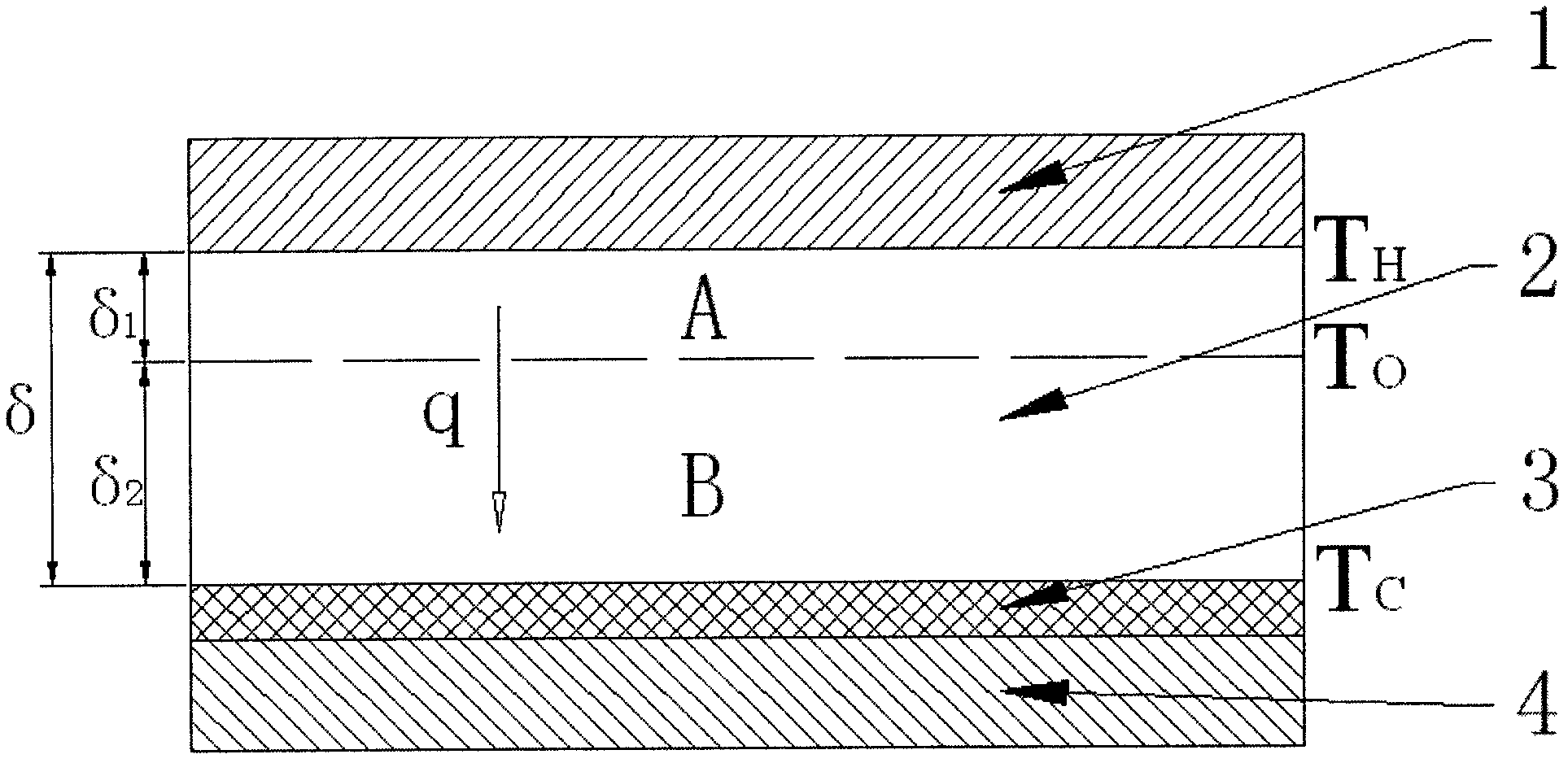
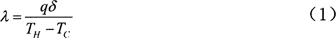
[0049] see figure 2 , which is a schematic diagram of the principle of the high-temperature thermal conductivity measurement method of the present invention. in accordance with figure 2 As shown, in the tested material sample, it is always possible to find the temperature T o material layer, and (T H +T C ) / 2o C . temperature is T o The material layer divides the material sample into two parts, A and B. Since it is a steady state heat transfer condition, the heat flux through part A of the material sample is equal to the overall heat flux q of the material sample. Due to the heat flux through part A of the material sample, and the T H , T o known, according to the formula

[0050] λ 2 = q δ 1 T H ...


PUM


Abstract

The invention relates to the field of thermal conductivity coefficient of a material, in particular to a method for measuring high temperature thermal conductivity coefficient. The method provided by the invention comprises the following steps of: firstly testing steady state thermal transfer thermal current density q of the material sample with the thickness Theta under the conditions that 'temperature difference is TH-TC and average temperature is (TH+TC) / 2'; then testing steady state thermal transfer thermal current density q1 of the sample in the first step under the conditions that 'the temperature difference is To-TC and the average temperature is (To+TC) / 2', wherein To can be in accordance with engineering requirements and is set to be a value close to TH in the first step, and To value is required to be less than TH value; and determining the thermal conductivity coefficient under the conditions that 'the temperature difference is TH-To and the average temperature is (TH+To) / 2' by combining a formula (1) and utilizing the thermal current density data acquired by the steps. In the invention, a T0 temperature layer in the material sample is selected, measurement accuracy can be relatively conveniently adjusted, measurement on the thermal conductivity coefficients of different temperature regions is realized, accurate measurement of the thermal conductivity coefficient at high temperature can be realized especially when T0 is close to the temperature of a hot plate, and the method provided by the invention is simple and convenient to operate and has greater practical application value.

Description

technical field [0001] The invention relates to the field of material thermal conductivity, in particular to a method for measuring high temperature thermal conductivity. Background technique [0002] Thermal conductivity is one of the basic thermophysical parameters of solid materials and an important physical parameter for evaluating the thermal insulation performance of materials. With the development of science, technology and industry, the thermal conductivity of materials has been applied to different fields, including: aerospace, microelectronics technology, nuclear energy technology, new material development and other high-tech fields, as well as petrochemical, steel metallurgy, building energy conservation and other industries field. For example, in the military field, all space vehicles go through the process of launching, orbiting, flying and even re-entering the atmosphere, and undergo different degrees of aerodynamic heating stages. Effective thermal control te...

Claims


Application Information

Patent Timeline
Patent Type & Authority Applications(China)
IPC IPC(8): G01N25/20
Inventor 秦强蒋军亮成竹
Owner CHINA AIRPLANT STRENGTH RES INST
Why Eureka
Try Eureka