Display device and display control method

A display device and time control technology, applied to static indicators, instruments, etc., can solve the problems of insufficient brightness and insufficient display of flash lights, etc., and achieve the effects of improving display quality, suppressing rapid changes, and preventing whitening

Inactive Publication Date: 2011-12-14
PANASONIC CORP
View PDF1 Cites 5 Cited by
  • Summary
  • Abstract
  • Description
  • Claims
  • Application Information

AI Technical Summary

Problems solved by technology

[0017] However, at this time, in a scene where the flash of a camera etc. suddenly emits light, due to the influence of the LPF, the brightness of the backlight for displaying the light of the flash cannot be sufficiently ensured, and there is a problem that the light of the flash cannot be fully displayed.

Method used


Image

  • Display device and display control method
  • Display device and display control method
  • Display device and display control method

Examples


Embodiment approach 1

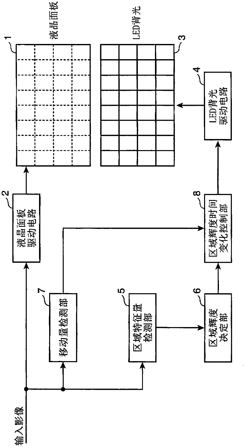
[0044] First, a liquid crystal display device according to Embodiment 1 of the present invention will be described. figure 1 It is a block diagram showing the overall configuration of the liquid crystal display device according to Embodiment 1 of the present invention. figure 1 The illustrated liquid crystal display device includes a liquid crystal panel 1, a liquid crystal panel drive circuit 2, an LED (Light Emitting Diode: Light Emitting Diode) backlight 3, an LED backlight drive circuit 4, an area feature detection unit 5, an area luminance determination unit 6, a moving Quantity detection part 7 and area luminance time change control part 8.

[0045] Although not shown in the figure, the liquid crystal panel 1 includes a plurality of gate lines, a plurality of source lines, switching elements and a plurality of pixel cells. and the intersections of multiple gate lines are arranged in a matrix, and a row of pixels in the horizontal direction constitutes a scanning line....

Embodiment approach 2

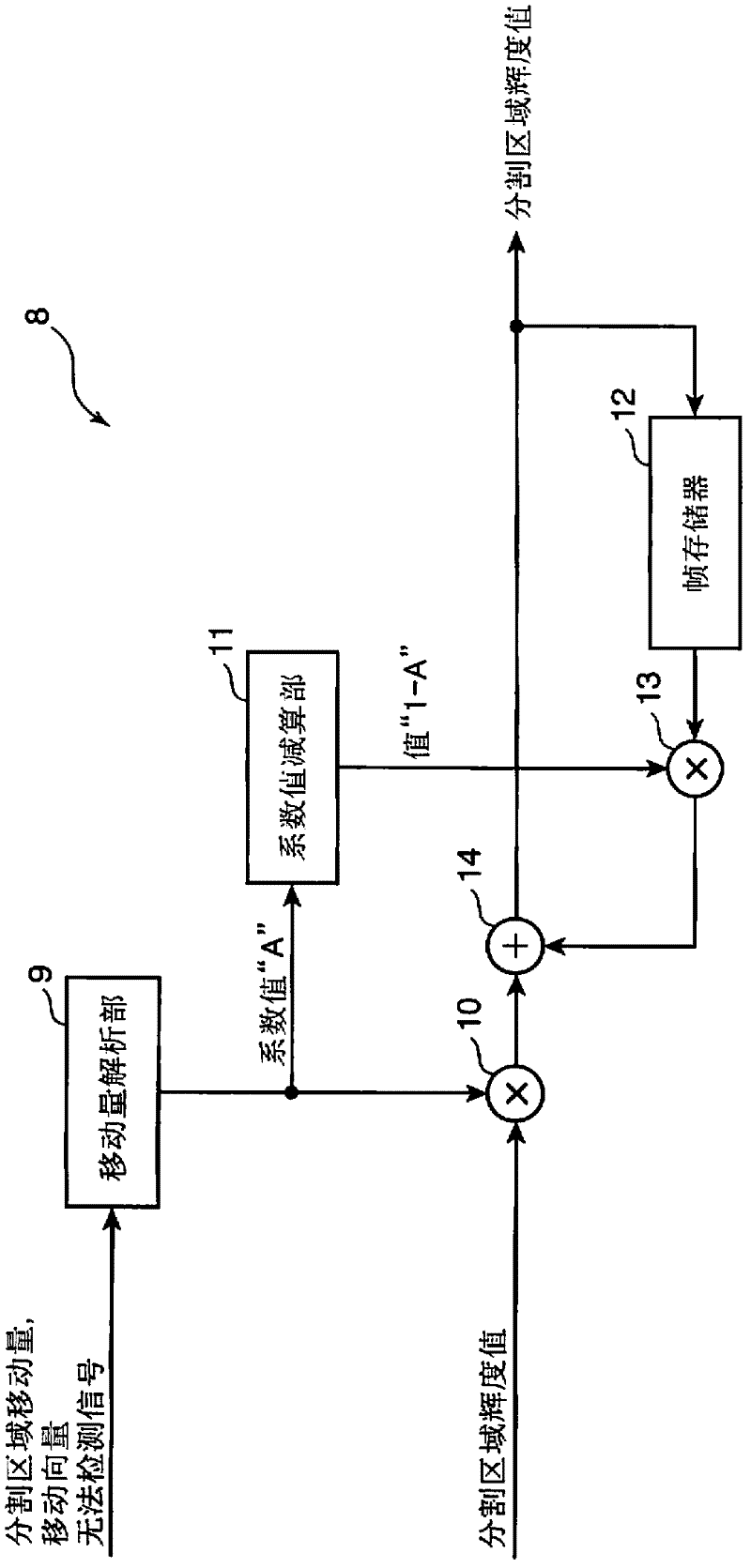
[0123] Figure 15 It is a block diagram showing the detailed configuration of the area luminance temporal change control unit 8 in the liquid crystal display device according to the second embodiment. In addition, the overall structure of the liquid crystal display device according to Embodiment 2 is the same as figure 1 The illustrated liquid crystal display device is the same, so description thereof will be omitted. In addition, in Figure 15 in, right with figure 2 The same components of the illustrated area luminance temporal change control unit 8 are denoted by the same reference numerals, and description thereof will be omitted.

[0124] Figure 15 The shown area luminance time change control unit 8 counts the motion vectors in the divided area that cannot be detected by the movement amount detection unit 7 as undetectable movement when it is determined that the movement amount detected by the movement amount detection unit 7 is equal to or greater than a predeterm...


PUM


Abstract

The invention provides a display device and a display control method capable of improving the display quality of images. The display device includes: an LED backlight (3) that divides the screen into a plurality of divided areas and illuminates each divided area; a movement amount detection unit (7) that detects the movement amount of each divided area of ​​an input image; An area luminance determination unit (6) for the reference luminance value of the divided area; an area luminance time change control unit (8) for determining the luminance control time of each image area required to reach the reference luminance value according to the amount of movement An LED backlight drive circuit (4) that drives the LED backlight (3) based on the luminance control time of each image area determined by the area luminance time change control unit (8).

Description

technical field [0001] The present invention relates to a display device for displaying images by modulating irradiation light from an illumination light source with a light modulation element, and a display control method for controlling the illumination light source. In particular, the present invention relates to a display device and a display control method that divides a screen into a plurality of regions and controls an illumination light source that illuminates each of the divided image regions. Background technique [0002] A liquid crystal display device using a liquid crystal display element (liquid crystal panel) as a light modulation element has an illumination light source on the back, and the transmittance of light emitted from the illumination light source is controlled by the liquid crystal panel to display an arbitrary image. [0003] Conventionally, there is a liquid crystal display device in which the display screen is divided into a plurality of divided a...

Claims


Application Information

Patent Timeline
Patent Type & Authority Applications(China)
IPC IPC(8): G09G3/36G02F1/133G09G3/20G09G3/34
CPCG09G2320/0646G09G2320/0247G09G2320/064G09G2310/0237G09G2360/16G09G2320/0261G09G2320/0238G09G2320/106G09G2320/0653G09G2340/16G09G3/3426
Inventor 中西敦士
Owner PANASONIC CORP
Why Eureka
Try Eureka