
Electrical appliance identification method and household user carbon emission measurement system using the method

An identification method and technology for electrical appliances, applied in the measurement of electrical variables, instruments, and electrical measurement, can solve the problems of carbon emissions, not considering the additional carbon emissions of electrical appliances, and complicated installation, achieving low investment, realizing ultra-power processing, Effects of Correcting Electricity Habits

Inactive Publication Date: 2011-12-14
HUAZHONG UNIV OF SCI & TECH
View PDF6 Cites 42 Cited by
  • Summary
  • Abstract
  • Description
  • Claims
  • Application Information

AI Technical Summary

Problems solved by technology

Although the corresponding purpose can be achieved in this way, the price is high, the installation is complicated, and the feasibility is poor.
[0004] In the current situation, household users lack the awareness of energy conservation, emission reduction and low-carbon consumption, and they have little or no consideration of the additional carbon emissions generated during the use of some electrical appliances, which may lead to excessive carbon emissions
Due to the low awareness of low-carbon consumption in the whole society and the misleading of certain aspects, it will lead them to unconsciously adopt some unreasonable lifestyles and destroy the construction of the entire environment unconsciously.

Method used


Image

  • Electrical appliance identification method and household user carbon emission measurement system using the method
  • Electrical appliance identification method and household user carbon emission measurement system using the method
  • Electrical appliance identification method and household user carbon emission measurement system using the method

Examples


Embodiment Construction

[0028] Provide an embodiment below in conjunction with accompanying drawing:

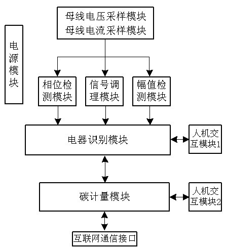
[0029] like figure 1 As shown, an electrical appliance identification method and a household user carbon emission metering system using the method: including a bus voltage sampling module, a bus current detection module, a phase detection module, a signal conditioning module, an amplitude detection module, a power supply module, and a human-computer interaction Modules 1 and 2, Appliance Identification Module, Carbon Metering Module.

[0030] The bus voltage sampling module is through a voltage sensor (the voltage sensor can be a voltage transformer, a voltage Hall sensor, etc.), and the bus current detection module is through a current sensor (the current sensor can be a current transformer, a current Hall sensor, a shunt, etc.) Convert the high voltage and large current on the grid side into low voltage and small current, and transmit it to the phase detection module, signal conditioning module a...


PUM


Abstract

The invention discloses an electrical appliance recognition method. The method is characterized in that: an electrical appliance is recognized according to a matching result of current characteristic parameter values. The invention further provides a household user carbon emission metering system applying the method. The metering system comprises a bus voltage sampling module, a bus current detection module, a phase detection module, a signal conditioning module, an amplitude detection module, an electrical appliance recognition module and a carbon metering module, wherein the bus voltage sampling module is connected with the input ends of the phase detection module, the signal conditioning module and the amplitude detection module respectively; the bus current detection module is connected with the input end of the signal conditioning module; the output ends of the phase detection module, the signal conditioning module and the amplitude detection module are connected with the input end of the electrical appliance recognition module; and the output end of the electrical appliance recognition module is connected with the carbon metering module. In the system, carbon emission is metered on the basis of accurate recognition of the electrical appliance, so that people are helped to set up the consciousness of energy saving, emission reduction and low-carbon consumption and correct incorrect power utilization habits.

Description

technical field [0001] The invention relates to a household electric load identification and carbon emission monitoring and measurement system, in particular to an electrical appliance identification method and a household user carbon emission measurement system applying the method. Background technique [0002] With the development of electronic technology, multi-functional energy meters with single-chip microcomputers as the core have gradually become popular. This type of energy meters has high measurement accuracy and calculation speed. Record the consumption, save the maximum demand of electric energy, set parameters, etc. But this is only limited to measuring the power consumption of all electrical appliances of the user, and cannot be accurate to each electrical appliance. And this type of meter is only based on the voltage and current amplitude of the power grid to measure and count the electric energy in the measurement method, so the function is relatively simple....

Claims


Application Information

Patent Timeline
IPC IPC(8): G01R31/00G01R22/06
Inventor 熊春李鑫朱石超程振尹仕李江晨
Owner HUAZHONG UNIV OF SCI & TECH
Learn More