
Initiation Control Method for Reducing Blasting Vibration Effect

A blasting vibration and control method technology, which is applied in the field of blasting, can solve the problems of aggravated blasting vibration hazards, large delay errors, and low delay accuracy, and achieve the effect of reducing blasting vibration effects and reducing blasting vibration effects

Inactive Publication Date: 2011-12-07
CHANGJIANG RIVER SCI RES INST CHANGJIANG WATER RESOURCES COMMISSION
View PDF2 Cites 16 Cited by
  • Summary
  • Abstract
  • Description
  • Claims
  • Application Information

AI Technical Summary

Problems solved by technology

[0003] The purpose of the present invention is to overcome the problem that the electric detonator, the plastic detonator detonator delay error is large, and the delay precision is low. Effectively reduce the impact of blasting vibration

Method used


Image

  • Initiation Control Method for Reducing Blasting Vibration Effect
  • Initiation Control Method for Reducing Blasting Vibration Effect
  • Initiation Control Method for Reducing Blasting Vibration Effect

Examples


Embodiment Construction

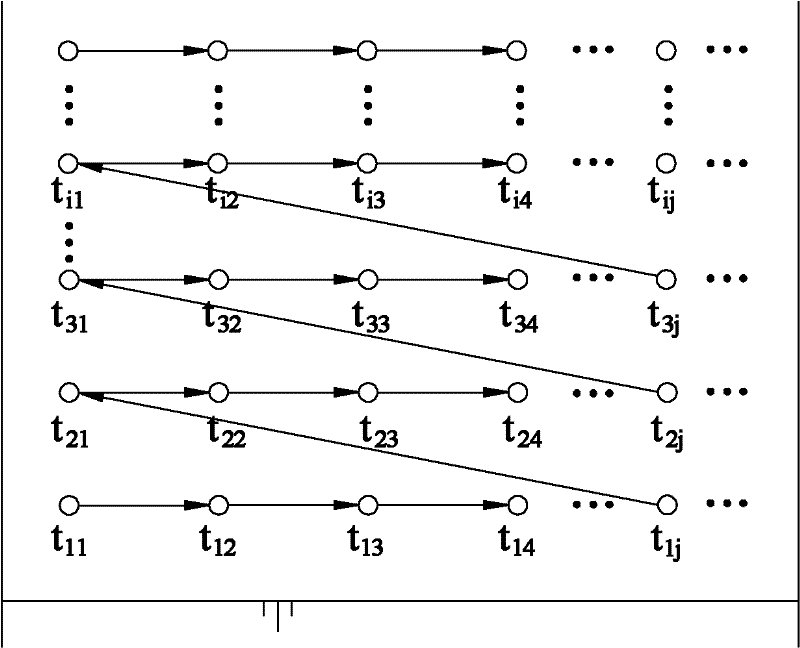
[0016] In the layout of the detonation network, the blastholes are divided into many rows according to their geographical location and detonation sequence. The detonation time difference between the detonators of adjacent holes in the same row is the delay between holes, and the detonation time difference of the detonators of adjacent holes in the same row is The delay time between holes is the same.

[0017] The time difference between detonating detonators between corresponding blastholes in adjacent rows in the detonating network is the inter-row delay.

[0018] Let the delay between holes be ΔT i , whose calculation formula is:

[0019] ΔT i = t i,(j+1) -t ij (i=2, 3, 4, . . . , j=1, 2, 3, . . . )

[0020] In the formula: i represents the row number, j represents the jth blast hole, t ij is the detonation time of the i-th row j-th blasthole in the detonation network, in milliseconds; t i,(j+1) is the detonation time of the (j+1)th blast hole in the i-th row in the ...


PUM


Abstract

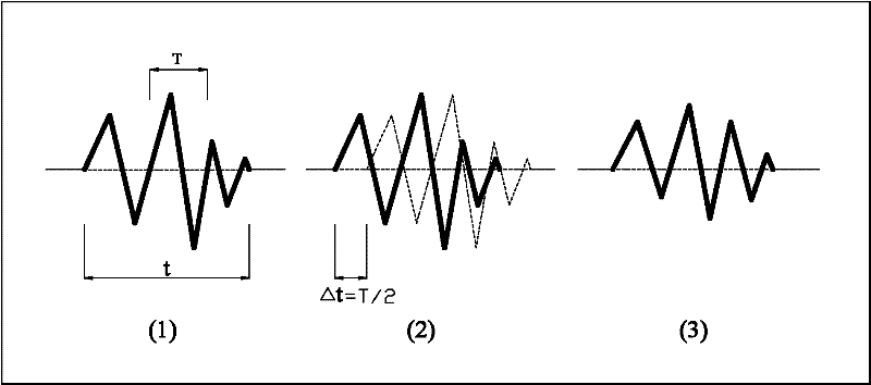
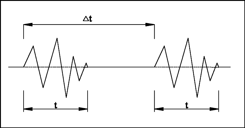
The invention discloses a detonation control method for reducing blasting vibration effect, which uses digital electronic detonators to reduce blasting vibration effects by controlling the number of each detonator section. One is: the selection of the number of detonator segments adopts the principle of mutual interference between blasting vibration peaks and troughs to reduce vibration, specifically: the delay time between the holes of each row of blast holes adjacent to the detonator detonator ΔTi = T / 2-1000*a / c, where T is the main vibration period of the blasting vibration, in milliseconds; ΔTi is the delay time between adjacent blastholes for sequential detonation, in milliseconds; a is the distance between blastholes, in meters; c is the propagation velocity of seismic waves in rocks, The unit is m / s; the inter-row delay between adjacent rows: ΔTj=nΔTi, ΔTj is the inter-row delay time, and the unit is millisecond; n is the number of adjacent front row detonator segments. The second method is: the selection of the number of each detonator section adopts the principle that the blasting vibration waves are independent of each other and vibration does not superimpose, that is, the inter-hole delay ΔTi=(1.0~1.5)t of sequentially detonating adjacent detonators.

Description

technical field [0001] The invention relates to an initiation control method for reducing the blasting vibration effect, which belongs to the field of blasting technology, in particular to a technology capable of effectively reducing the blasting vibration effect. Background technique [0002] In engineering blasting, fire detonators, electric detonators, and plastic detonators are commonly used detonating materials at present. The first-generation detonation technology represented by fire detonators has been eliminated due to the large potential safety hazards; the second-generation detonation technology represented by electric detonators is limited to a certain extent due to the limited number of detonator segments; The third-generation detonation technology represented by plastic nonel has played an important role in controlling the blasting vibration effect and increasing the scale of primary detonation. It is still the most commonly used detonation technology at this st...

Claims


Application Information

Patent Timeline
IPC IPC(8): F42D1/05
Inventor 赵根刘美山吴新霞郑武吴从清
Owner CHANGJIANG RIVER SCI RES INST CHANGJIANG WATER RESOURCES COMMISSION
Learn More