
A processing method and a pocket hole processing device for an integral cage of a wind power equipment bearing

A technology for wind power equipment and processing devices, applied in positioning devices, metal processing equipment, metal processing machinery parts, etc., can solve problems such as difficult guarantee of technical requirements, and achieve the effect of ensuring accuracy

Inactive Publication Date: 2011-12-07
田天红
View PDF6 Cites 11 Cited by
  • Summary
  • Abstract
  • Description
  • Claims
  • Application Information

AI Technical Summary

Problems solved by technology

[0005] In the existing processing technology, since the cold-rolled sheet has processed 60 to 150 equally arranged rolling element pockets during laser cutting and blanking, it is a long semi-finished product, such as figure 1 As shown, in the subsequent "rough and fine rounding forming" and "integrating" processes, due to the shape of the part with pockets and the connection part between the two pockets (that is, the part 1 that is easy to produce polygonal circles), etc. 1. Different structures cause inconsistency in rounding and bending deformation, that is, the phenomenon of "polygonal circle", which makes it difficult to guarantee the technical requirements for the roundness of the pocket hole of the finished product of the overall cage (medium diameter tolerance ± 0.5mm, roundness 0.8mm)

Method used


Image

  • A processing method and a pocket hole processing device for an integral cage of a wind power equipment bearing
  • A processing method and a pocket hole processing device for an integral cage of a wind power equipment bearing
  • A processing method and a pocket hole processing device for an integral cage of a wind power equipment bearing

Examples


Embodiment Construction

[0038] The processing method of the integral cage of the wind power bearing includes the steps of blanking, rough rounding, welding, fine rounding, and shaping; it also includes the step of processing pocket holes; A strip-shaped plate without pockets; the step of processing the pockets is located after the fine rounding step and before the shaping step.

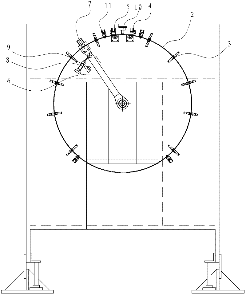
[0039] Such as figure 2 As shown, the wind power bearing overall cage pocket hole processing device mainly includes a support mechanism 3, a radial positioning mechanism 4, an axial positioning mechanism 5, a drive cage moving mechanism, a boom limit mechanism, and a cage movement limit mechanism 11.

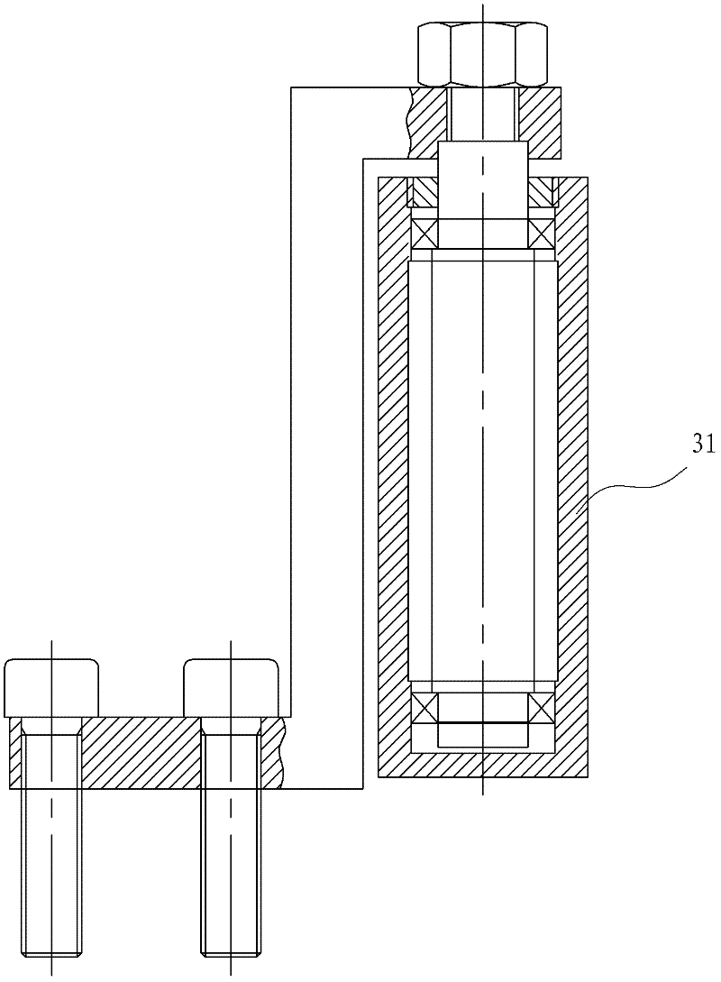
[0040] Such as image 3 , 4 As shown, the support mechanism 3 includes 20 pairs of rollers 31 with relatively fixed positions; each pair of rollers is arranged in parallel and the axial direction is parallel to the axial direction of the cage 2, and there is a gap for placing the cage 2 between the two rollers 31; multiple...


PUM


Abstract

The invention relates to a pocket machining device and a method for machining an integral bearing retainer of wind power equipment. The machining method comprises the steps of material feeding, rough rounding, welding, fine rounding and shaping in sequence, as well as pocket machining; the machining method is characterized in that: in the material feeding step, a cold-rolled plate is cut into a straight-strip-shaped pocket-free plate; the pocket machining step is performed after the fine rounding step and before the shaping step; and the roundness of pockets on the retainer can be ensured, the pockets can be prevented from deforming and generating multi-edge round, and the precision of the pockets on the retainer can be guaranteed. The pocket machining device comprises a supporting mechanism, a radial positioning mechanism, an axial positioning mechanism, a retainer driving and moving mechanism and a movable arm limiting mechanism, as well as a hydraulic control system which is used for controlling a first cylinder, a second cylinder, a movable arm cylinder and a third cylinder. The functions of clamping, positioning, equal-distance feeding, compressing and discharging and the like of the retainer after being welded into a whole can be realized during pocket laser cutting and machining.

Description

technical field [0001] The invention relates to the technical field of bearing cage processing, in particular to a pocket hole processing device for an integral cage of a wind power equipment bearing. Background technique [0002] The wind power equipment bearing integral cage has thin material thickness (material thickness 5-10mm), narrow finished product width (material width 50-100mm), super large outer diameter (outer diameter Φ1500-3500mm), and many rolling element pockets (generally 60 to 150) and closely arranged; overall high precision, poor rigidity, easy to deform; special structure, complex conditions of use. Once installed in the wind power equipment bearings, the possibility of disassembly, repair and replacement is lost. [0003] The current production process of the wind power equipment bearing integral cage is as follows: [0004] Laser cutting blanking of cold-rolled sheet metal (including rolling element pockets)→surface processing→rough rounding→welding→...

Claims


Application Information

Patent Timeline
IPC IPC(8): B23P15/00B23Q3/00
Inventor 田天红
Owner 田天红
Learn More