
Dust bucket

A technology of dust collection bucket and dust, which is applied in the field of dust collection bucket, which can solve the problems of inconvenient daily use, poor sealing of the bottom of the dust collector, dust leakage, etc., achieve high dust discharge cleanliness, avoid re-pollution and unpleasantness, The effect of low operating point

Inactive Publication Date: 2016-03-02
NANJING LG PANDA APPLIANCES
View PDF5 Cites 0 Cited by
  • Summary
  • Abstract
  • Description
  • Claims
  • Application Information

AI Technical Summary

Problems solved by technology

[0010] The opening method of the bottom cover of the dust collection bucket in the prior art needs to press the push rod to push out the bottom cover and dump the dust. Since the chassis is fixed with a buckle, the user needs to use a lot of force to press the push rod when opening the bottom cover. very inconvenient for daily use
[0011] And now the bottom of the dust collection bucket adopts the open and close shaft connection method. Due to the plastic deformation of the bottom cover during processing, the sealing of the bottom of the dust collector is not good, and there is a serious dust leakage phenomenon in daily use.

Method used


Image

  • Dust bucket
  • Dust bucket
  • Dust bucket

Examples


no. 3 example

[0050] The chassis is fixed above the bottom plate of the base, that is, compared with the first embodiment, the annular grooves 38, 39 are formed above the bottom plate of the base, preferably, it only needs to set an inner circular Annular groove, and the chassis is buckled between the cylindrical side wall 29 and the inner circular annular groove and a narrow cavity that can accommodate the sliding slider 30 is formed between the two, the fixing method of the side wall and the through hole 1. The setting method of the sliding slider 30 is the same as that described above, and will not be repeated here.

[0051] The working process of the vacuum cleaner of the present invention is the same as that described above. When the dust in the dust collection bucket reaches a certain level, the dust collector is removed from the vacuum cleaner, and the push button at the bottom of the dust collection bucket above the garbage can is used to pass through the dust collector. The holes a...


PUM


Abstract

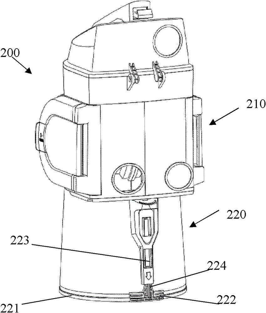
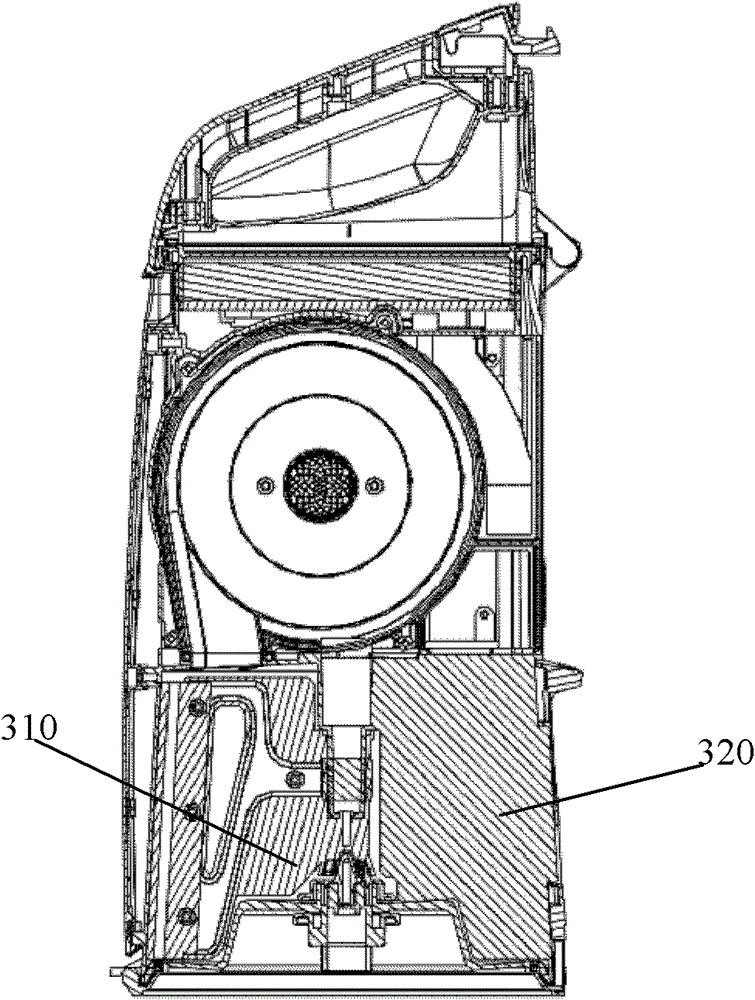
A dust collection barrel, the bottom of which is provided with an opening to discharge the dust accumulated therein, the bottom cover is fixedly connected with the dust collection barrel and closes the bottom opening of the dust collection barrel, and the bottom cover includes a fixedly connected base and a chassis , the base and the chassis are symmetrically formed with through holes up and down, and a narrow cavity is formed between the adjacent surfaces of the base and the chassis to accommodate the sliding block, and the sliding block can be selected Close or open the through hole of the bottom cover. The method of dumping dust at the bottom has a high degree of dust discharge and is easy to operate without separating the dust separator from the dust collection bucket, and the operating point is low, which avoids re-pollution and discomfort to users caused by flying dust. And the dust collecting bucket of the present invention is plugged inside the bottom support of the bottom cover, and concave-convex grooves are arranged at the plug-in parts, and the track of the sliding slider is also provided with concave-convex grooves, which prevents dust from leaking from the bottom.

Description

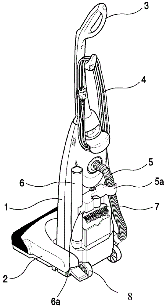
technical field [0001] The invention relates to a dust collecting bucket, in particular to a bottom dust dumping structure of the dust collecting bucket. Background technique [0002] In general, a vacuum cleaner is a device for sanitation that uses vacuum pressure generated by a vacuum motor installed in its body to suck dust-containing gas and then filters the dust in the gas. [0003] figure 1 It is a three-dimensional schematic diagram of a vacuum cleaner in the prior art. Such as figure 1 As shown, the vacuum cleaner includes a vacuum cleaner body 1 with a suction force generator therein, a dust collector for separating dust from the introduced air and storing the separated dust; a bottom cover 2, which includes a vacuum cleaner containing dust The suction nozzle 9 through which the gas passes; and the electric wire 4 for power supply; the handle 3 and the roller 8 that allow the user to operate the vacuum cleaner; the connecting hose 5 that connects the suction nozz...

Claims


Application Information

Patent Timeline
Patent Type & Authority Patents(China)
IPC IPC(8): A47L9/10
Inventor 张旭瀛
Owner NANJING LG PANDA APPLIANCES
Learn More