Lighting device, display device and television receiver
A technology of lighting device and light source, applied in the fields of lighting device, display device and TV receiving device, can solve the problems of thermal expansion of light guide plate, uneven brightness of light guide plate, thermal shrinkage, etc., and achieve the effect of brightness stabilization
- Summary
- Abstract
- Description
- Claims
- Application Information
AI Technical Summary
Problems solved by technology
Method used
Image
Examples
Embodiment approach 1
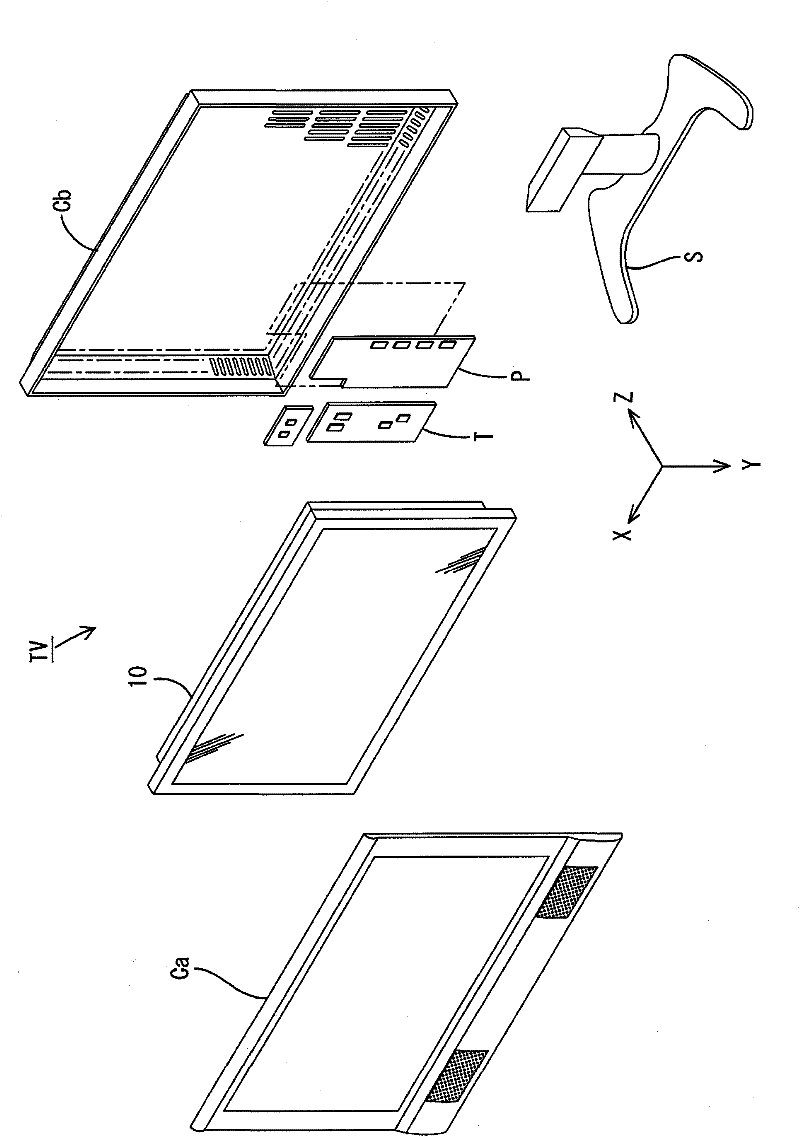
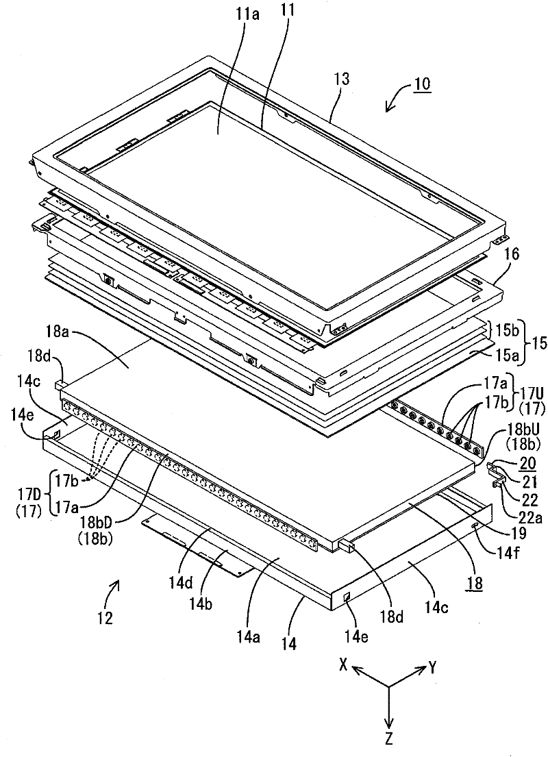
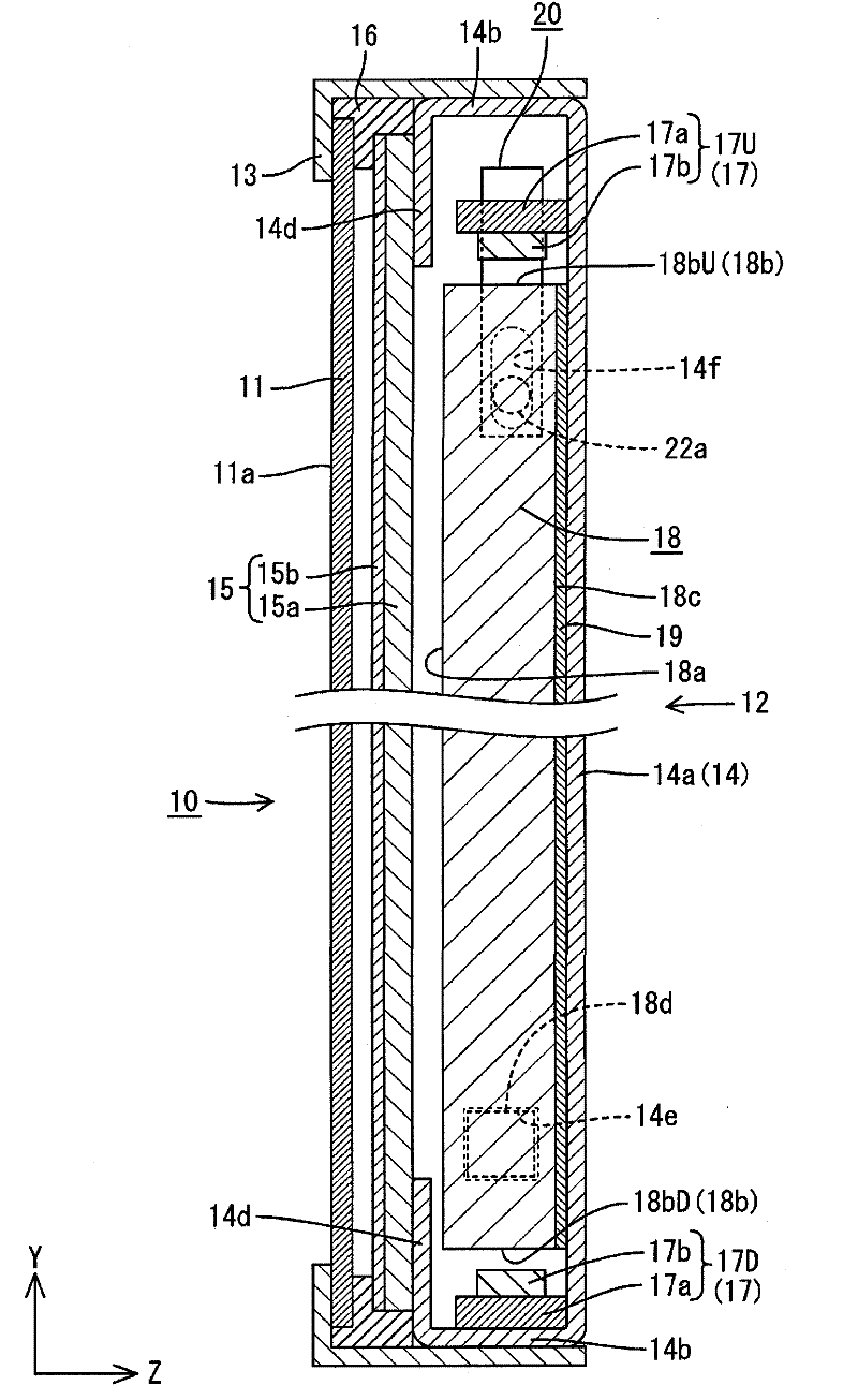
[0045] according to Figure 1 to Figure 6 Embodiment 1 of the present invention will be described. In this embodiment, a liquid crystal display device 10 is exemplified. In addition, X-axis, Y-axis, and Z-axis are shown in a part of each drawing, and the direction of each axis is drawn as the direction shown in each drawing. Wherein, the Y-axis direction is consistent with the vertical direction, and the X-axis direction is consistent with the horizontal direction. In addition, unless otherwise specified, descriptions about up and down are based on the vertical direction. Additionally, the figure 2 The upper side shown is the front side, and the lower side in the figure is the back side.
[0046] The television receiver TV of this embodiment is such as figure 1 As shown, it includes a liquid crystal display device 10 (display device), two front and back cabinets Ca, Cb for storing the liquid crystal display device 10, a power supply P, and a tuner T. The display surface...
Embodiment approach 2
[0083] according to Figure 7 or Figure 8 Embodiment 2 of the present invention will be described. In this Embodiment 2, the case where the guide mechanism of the support member 20A and the base 14A is changed is shown. In this second embodiment, the same reference numerals are used for the same parts as those in the first embodiment described above, and an additional letter A is added at the end thereof, and redundant descriptions of the structures, operations, and effects are omitted.
[0084] Support member 20A such as Figure 7 As shown, it includes a main body portion 21A formed in a crank shape when viewed from the side, and an extension portion 22A protruding from an end portion of the main body portion 21A. The main body portion 21A includes: a pair of horizontal plate portions 21aA, 21bA along the Z-axis direction; and a vertical plate portion 21cA connecting ends of the two horizontal plate portions 21aA, 21bA and extending along the Y-axis direction. Among them...
Embodiment approach 3
[0088] according to Figure 9 or Figure 10 Embodiment 3 of the present invention will be described. In this Embodiment 3, the fixed position of the light guide plate 18B, the number of installations of the follower mechanism, etc. are changed. In this third embodiment, the same reference numerals are used at the same parts as those in the first embodiment described above, and an additional letter B is added at the end thereof, and repeated descriptions of the structures, operations, and effects are omitted.
[0089] Fixed protrusion 18dB as Figure 9 As shown, fixing holes 14eB for receiving the fixing protrusions 18dB are formed in both short side plates 14cB of the base 14B at approximately the center in the vertical direction of both short side surfaces of the light guide plate 18B. Therefore, when the light guide plate 18B thermally expands or contracts, the vertical upper surface (light incident surface 18bUB) and lower surface (light incident surface 18bDB) of the li...
PUM
 Abstract
Description
Claims
Application Information
 - R&D Engineer
- R&D Manager
- IP Professional
- Industry Leading Data Capabilities
- Powerful AI technology
- Patent DNA Extraction
Browse by: Latest US Patents, China's latest patents, Technical Efficacy Thesaurus, Application Domain, Technology Topic, Popular Technical Reports.
© 2024 PatSnap. All rights reserved.Legal|Privacy policy|Modern Slavery Act Transparency Statement|Sitemap|About US| Contact US: help@patsnap.com


