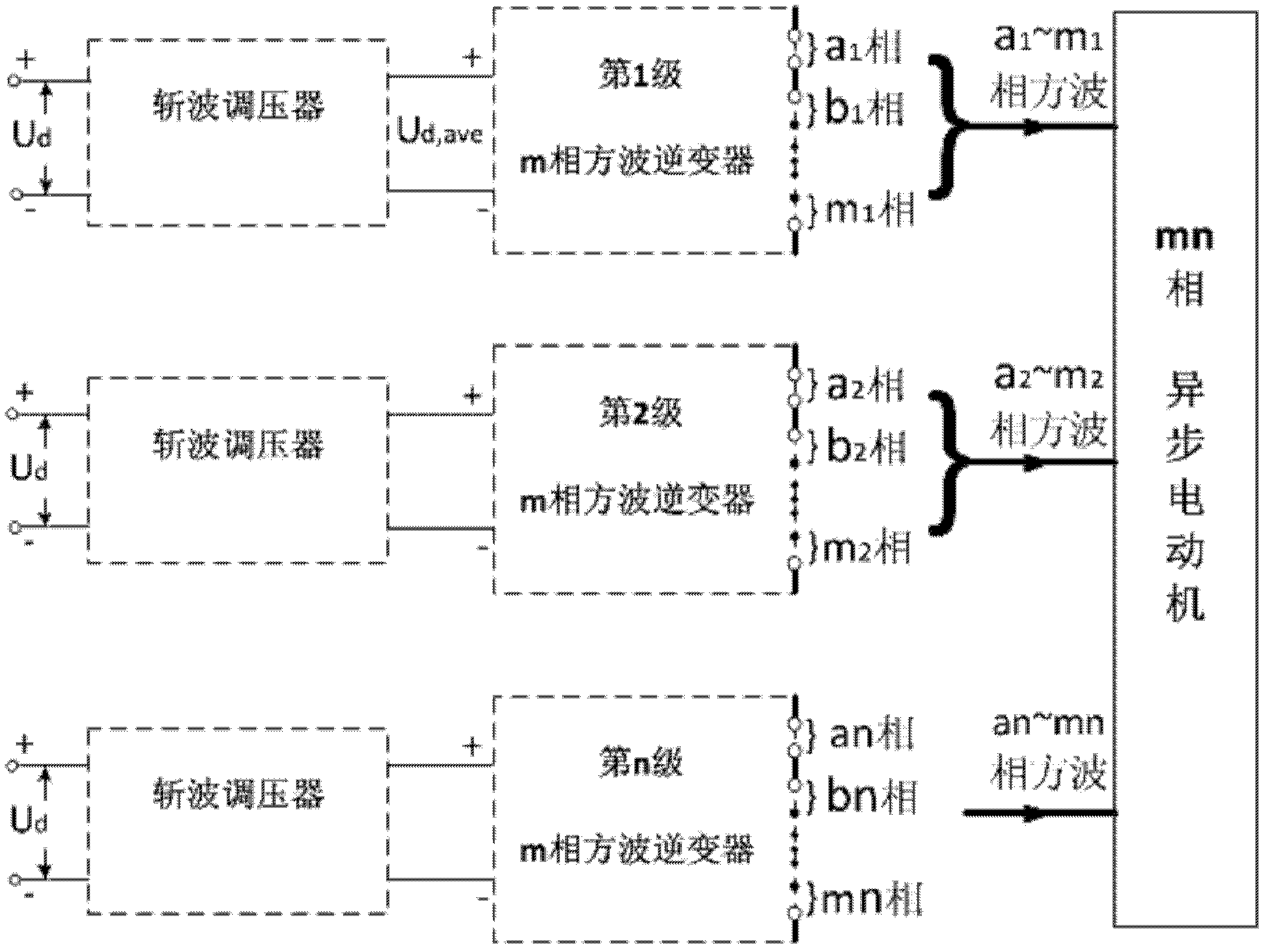
Multiphase square wave inverter realizing commutation by utilizing insulated gate bipolar transistors (IGBT) and consisting of thyristors
A converter transformer and inverter technology, which is applied to the irreversible DC power input into AC power output, AC power input into DC power output, and output power conversion devices, etc. The high cost of the inverter and the complexity of the circuit can reduce the insulation stress, reduce the loss and simplify the circuit.
- Summary
- Abstract
- Description
- Claims
- Application Information
AI Technical Summary
Problems solved by technology
Method used
Image

Examples
specific Embodiment 1
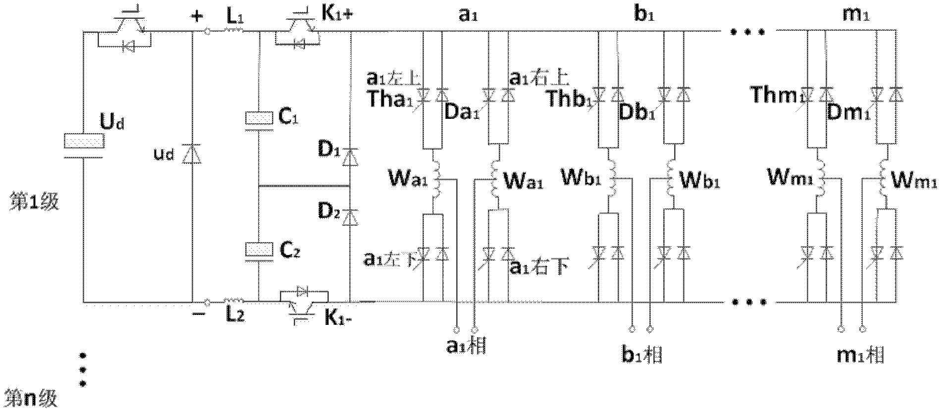
[0017] The circuit diagram of this specific embodiment is as figure 2 shown. Each stage of inverter contains m-phase frequency-variable square wave voltage generators, and each phase is a single-phase full bridge, including two pairs of upper and lower bridge arms. Each bridge arm consists of a thyristor Th and an antiparallel diode D. Two sets of diagonal bridge arms in each single-phase full bridge work in turn at 180°, and output a 180° square wave AC voltage. The output voltage is applied to a phase independent winding of the asynchronous motor. The m-phase square wave voltage is output in each inverter, and the phases are different from each other by 360 / m degrees.
[0018] The input terminal of each stage inverter is connected with a filter circuit composed of L1, C1, L2, and C2 and commutation switches K1+, K1-. The filter circuit composed of L1, C1, L2, and C2 basically filters the input DC pulse wave. The commutation switches K1+ and K1- are always on normally, ...
specific Embodiment 2
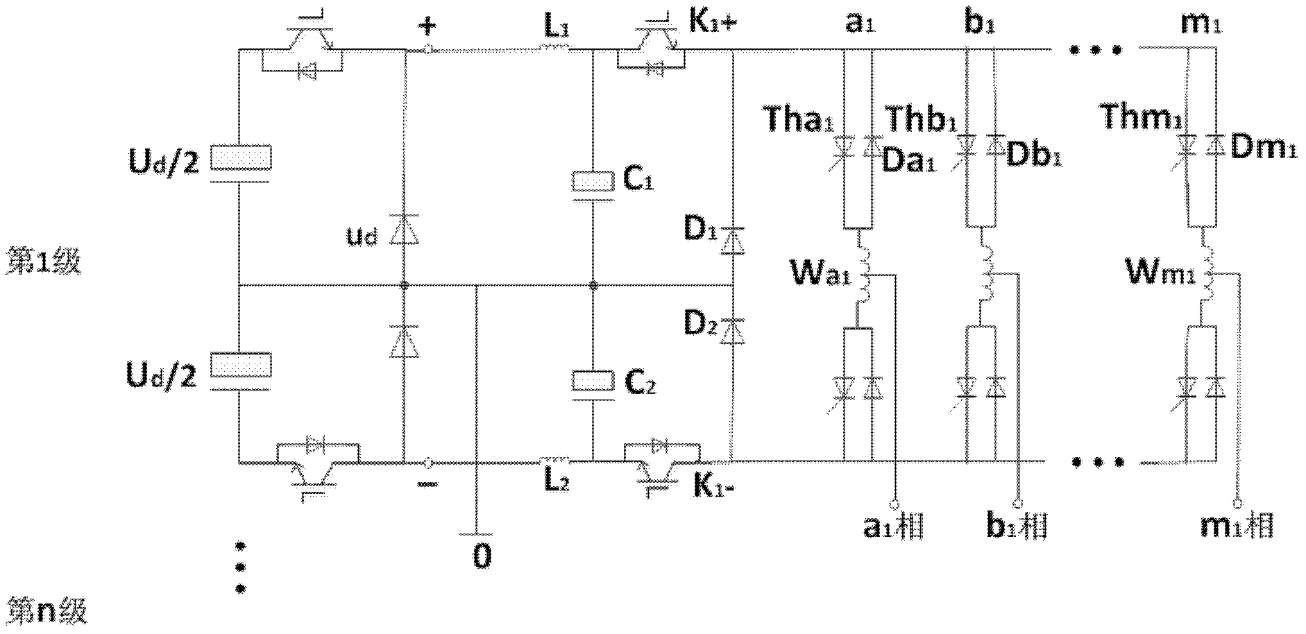
[0023] The circuit diagram of this specific embodiment is as image 3 shown. Compared with the specific embodiment 1, the difference is that the DC power supply not only outputs the + and - terminals, but also outputs the middle terminal (ie, the neutral line), and allows a certain neutral current to flow through, and the m phase of the inverter is changed to a half bridge. Each half-bridge includes two bridge arms; each bridge arm is composed of a thyristor and an anti-parallel diode, and a secondary winding W of a converter transformer is connected in series between the upper and lower bridge arms of each half-bridge. The circuit structure is the same as that of Embodiment 1. The square wave voltage can be input to the m-phase motor winding. At this time, the independent m-phase winding of the motor is connected in a star connection, and the midpoint of the star is connected to the neutral line of the DC power supply.
PUM
 Abstract
Description
Claims
Application Information
 - Generate Ideas
- Intellectual Property
- Life Sciences
- Materials
- Tech Scout
- Unparalleled Data Quality
- Higher Quality Content
- 60% Fewer Hallucinations
Browse by: Latest US Patents, China's latest patents, Technical Efficacy Thesaurus, Application Domain, Technology Topic, Popular Technical Reports.
© 2025 PatSnap. All rights reserved.Legal|Privacy policy|Modern Slavery Act Transparency Statement|Sitemap|About US| Contact US: help@patsnap.com