Waterproof self-heating floor system, and waterproof self-heating floors and self-heating assemblies thereof

A self-heating component, waterproof technology, applied in the field of architectural decoration, can solve problems such as unmentioned, burned floors, and unsolved waterproof problems of the floor system

Active Publication Date: 2011-11-23
启东市天汾电动工具技术创新中心
View PDF9 Cites 12 Cited by
  • Summary
  • Abstract
  • Description
  • Claims
  • Application Information

AI Technical Summary

Problems solved by technology

Among the above three installation methods, the "composite floor" in the third method covers a wide range. For example, laminate flooring is a kind of balanced paper layer, density board, decorative paper layer and wear-resistant paper from bottom to top Layers are formed by hot pressing, so structurally speaking, this kind of composite floor cannot pre-embed the heating wire, so those skilled in the art cannot implement the third installation method of the heating wire in this document.
As for the first two installation methods, there is a problem of making complicated troubles
[0007] Again, it is proposed in this document that the first connector, the second connector, the plug, the first joint and the second joint are all features of a waterproof structure, but it does not solve the waterproof problem of the entire floor system
Although the first joint and the second joint adopt a waterproof structure, there is no mention of how to solve the problem of waterproofing the connection between the two joints and the heating wire, nor does it involve the connection between the two joints and the floor board. The problem of sealing and waterproofing, when the floor system is not energized for a period of time, the water vapor in the air will enter the interior of the floor from the gap between the joint and the floor body, and condense at the joint between the joint and the heating wire. When the power is turned on, there will be serious leakage, which will cause the touch protector to trip immediately. If the touch protector is not installed, it will cause overheating or even burn the floor due to the generation of large current

Method used


Image

  • Waterproof self-heating floor system, and waterproof self-heating floors and self-heating assemblies thereof
  • Waterproof self-heating floor system, and waterproof self-heating floors and self-heating assemblies thereof
  • Waterproof self-heating floor system, and waterproof self-heating floors and self-heating assemblies thereof

Examples


Embodiment 1

[0328] (Example 1, self-heating component)

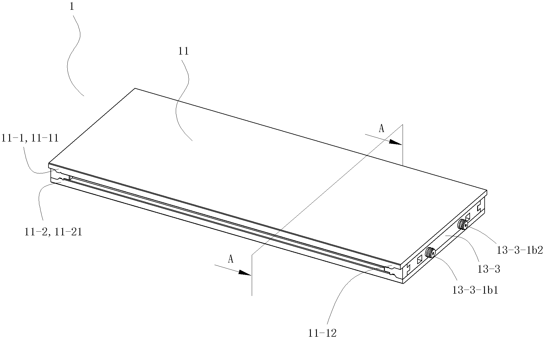
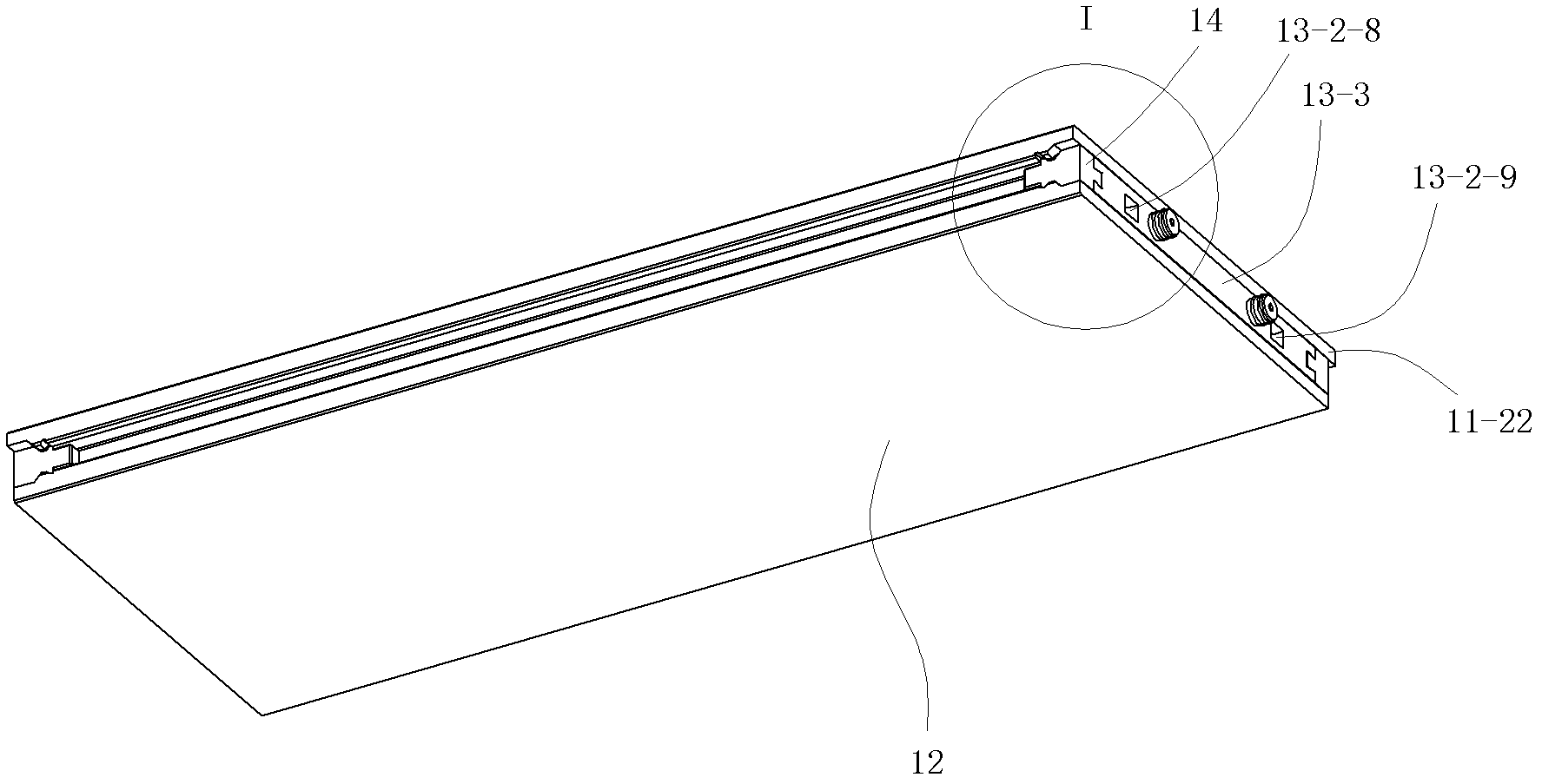
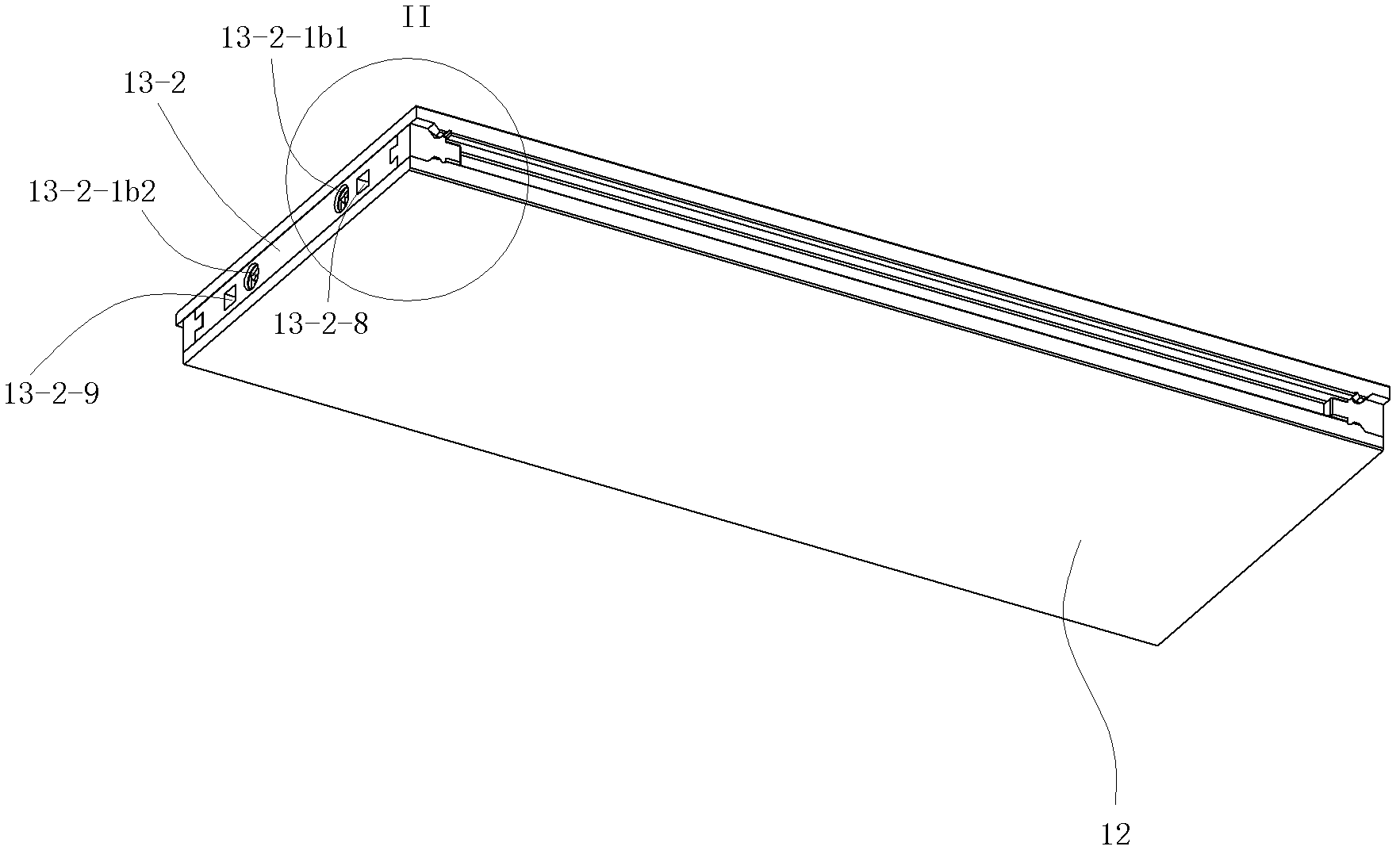
[0329] See Figure 12 and Figure 13 The self-heating component 13 is a waterproof electric heating component, and the self-heating component 13 includes a transmission unit, a heating sheet 13-1, and socket parts 13-2 and double plug parts 13-3 respectively located at the left and right ends of the heating sheet 13-1. The transmission unit of the self-heating component 13 is composed of a waterproof live wire and a waterproof neutral wire, and the transmission unit of the self-heating component 13 includes two wires 13-4. The socket part 13-2 is a part that can be plugged and fixedly electrically connected with the double plug part 13-3 of the self-heating component 13 of the corresponding adjacent waterproof self-heating floor 1 during use, and is connected with each other in a sealed and waterproof connection; the double plug The part 13-3 is a part that can be plugged and fixedly connected with the double plug part 13-3 of the...

Embodiment 2

[0349] (Example 2, self-heating components)

[0350] See Figure 13 The rest of the self-heating assembly 13 of this embodiment is the same as that of Embodiment 1, except that the conductive copper sheet 13-2-2 at the live wire end is located at the left connecting section 13-1a of the front heating sheet 13-11 The front end of the front is electrically connected to the first copper member 13-2-3c, and the first copper member 13-2-3c is then electrically connected to the tail of the fire wire copper pin 13-2-3a, and the first copper member 13-2 -3c is electrically connected to the left end of the first electric wire 13-41 of the transmission unit by welding; the corresponding parts involved in the above structure constitute the first electrical connection component 13a1 on the socket side.

[0351] The tail end on the right side of the neutral line copper pin 13-2-3b is electrically connected to the second copper member 13-2-3d, and the second copper member 13-2-3d is then ...

Embodiment 3

[0354] (Example 3, self-heating components)

[0355] See Figure 26 to Figure 28 , the rest of the self-heating assembly 13 of the present embodiment is the same as that of Embodiment 1, the difference is that: the waterproof live wire and the waterproof zero wire of the transmission unit of the self-heating assembly 13 all include two conductive copper sheets 13-6 , aluminum foil 13-5 and polyvinyl chloride sheet 13-8. Each conductive copper skin 13-6 is fixed on the lower surface of the electric heater 13-1 from below, and the lower surface of each conductive copper skin 13-6 is coated with conductive glue. The shape of the aluminum foil 13-5 is the same as that of the strip-shaped conductive heating layer 13-1-1 of the electric heating sheet 13-1, and is located below the electric heating sheet 13-1, and covers the strip-shaped conductive heating layer 13-1-1 from below. 1, and the upper surfaces of the left and right ends of the aluminum foil 13-5 are electrically conne...


PUM


Abstract

The invention discloses a waterproof self-heating floor system, comprising waterproof self-heating floors, connecting pieces and a power supply system. The power supply system is a power supply circuit. The quantity of the waterproof self-heating floors can meet the demand on the laying area; each waterproof self-heating floor comprises a floor main body and a self-heating assembly. The front side and the rear side of each floor main body are provided with connecting parts for connecting with the adjacent waterproof self-heating floors through the connecting pieces when the floor main body is used. Each self-heating assembly is a waterproof electric heating assembly. A socket part and a dual-plug part are respectively arranged on two ends of each self-heating assembly; when being used, the socket part is a waterproof connecting part which can be electrically connected in a mutual splicing fixation way and mutually sealed with the dual-plug part of the self-heating assembly of the corresponding adjacent waterproof self-heating floor. All the waterproof self-heating floors in the same row are electrically connected to the power supply circuit in parallel; and each waterproof self-heating floor is an independent heating unit which has no influence on the other units and is safe and reliable during the use.

Description

technical field [0001] The invention relates to a product in the field of building decoration, in particular to a waterproof self-heating floor system, a waterproof self-heating floor and a self-heating component thereof. Background technique [0002] At present, the form of self-heating floor is electric heating floor. Electric heating floor has become a new heating method. It is to lay electric heating material in the floor and heat the floor by heating the electric heating material. [0003] Chinese patent document CN1034826C (application number 92114554.3) discloses an electric heating floor. The floor is provided with two through holes in the horizontal direction in the floor board, and the electric heating wire is inserted into the through holes. The holes are dislocated and the heating wire is worn off, and the port of the through hole adopts a bell mouth. In order to be safer, the floor boards can be added with flame retardant materials, or the floor boards can be p...

Claims


Application Information

Patent Timeline
Patent Type & Authority Applications(China)
IPC IPC(8): H05B3/28H05B3/04F24D13/02E04F15/02
Inventor 葛林葛鑫琰
Owner 启东市天汾电动工具技术创新中心
Why Eureka
Try Eureka