Chain Tensioner

A technology for tensioners and chains, applied in belts/chains/gears, mechanical equipment, transmissions, etc., which can solve the shape that is difficult to assemble and disassemble, the rattling effect is small, and the shape of the tensioner body is large, etc. problem, achieve miniaturization and reduce manufacturing cost

Active Publication Date: 2011-11-23
TSUBAKIMOTO CHAIN CO
View PDF6 Cites 5 Cited by
  • Summary
  • Abstract
  • Description
  • Claims
  • Application Information

AI Technical Summary

Problems solved by technology

[0005] However, in the ratchet mechanism of this known chain tensioner, the excessive chain tension caused by the temperature change of the engine, etc. also limits the movement of the plunger to the accommodation direction, thereby causing the sintering of the plunger and the excessive chain tension. Traveling under high tension causes the burden on the chain and the problem of increased noise
[0006] Therefore, according to the imaginary maximum value of the movement of the plunger to the accommodation direction caused by excessive chain tension, a set amount of backlash is set on the ratchet mechanism, but there is still a larger amount of backlash, which reduces the rattling when the engine starts. The problem that the effect of Dasheng will be smaller
[0007] In addition, since the retreat-side gentle slope of the concave-convex groove provided on the outer periphery of the plunger is formed at a single set inclination angle with respect to the protruding direction of the plunger, the elastic diameter-expanding action of the engagement member composed of a ring, that is, the spring modulus If the forward movement of the plunger does not work, the forward speed of the plunger will change due to the enlarged diameter position of the joint member composed of the ring, and the responsiveness of the damping force will change irregularly, so that the plunger cannot move smoothly. Forward motion, rattling noise
[0008] In addition, when the engaging member provided on the tensioner body is composed of a cam mechanism having a protruding portion outside the tensioner body, the structure is complicated, the tensioner body has a large shape, and it is difficult to manufacture it so that it can be assembled. and disassembled shape
Furthermore, due to various conditions of use, it is necessary to design ratchet mechanisms with different characteristics, and the entire chain tensioner must also be designed to have characteristics suitable for the conditions of use, resulting in an increase in manufacturing costs.

Method used


Image

  • Chain Tensioner
  • Chain Tensioner
  • Chain Tensioner

Examples


no. 1 Embodiment

[0104] Hereinafter, the chain tensioner according to the first embodiment of the present invention will be described based on the drawings.

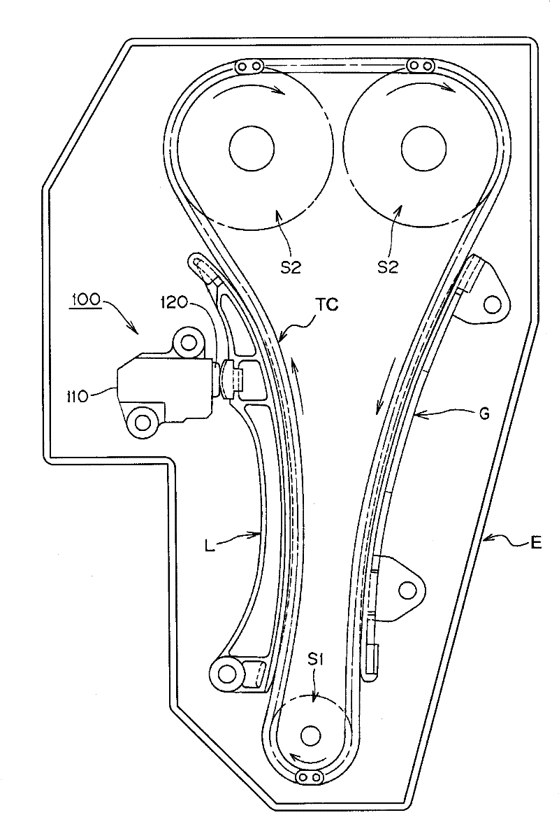
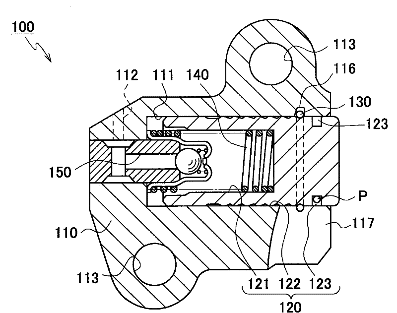
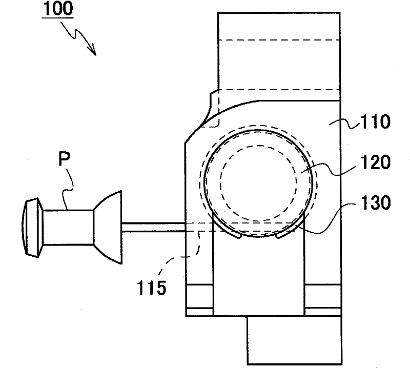
[0105] in, figure 1 It is a usage diagram of the chain tensioner according to the first embodiment of the present invention, figure 2 It is a schematic cross-sectional view showing the chain tensioner according to the first embodiment of the present invention, image 3 It is a front view of the chain tensioner according to the first embodiment of the present invention, Figure 4 for figure 2 Schematic diagram of the plunger used in the chain tensioner shown, Figure 5 is the schematic diagram and partial enlarged diagram of the elastic ring, Figure 6 for figure 2 An enlarged illustration of the ratchet mechanism of the chain tensioner shown, Figure 7 for Figure 5 Illustration of the ring deformation characteristics of the shown elastic ring. in addition, Figure 8 to Figure 9 It is an operation diagram when a load in the ...

no. 2 Embodiment

[0143] Hereinafter, a chain tensioner 200 according to a second embodiment of the present invention will be described based on the drawings.

[0144] Figure 22 It is a schematic cross-sectional view showing the chain tensioner according to the second embodiment of the present invention, Figure 23 It is a front view of the chain tensioner according to the second embodiment of the present invention.

[0145] Fig. 24 is the elastic ring used in the second embodiment of the present invention, (a) is its front view, (b) is its side view.

[0146] Here, comparing the chain tensioner 200 of the second embodiment of the present invention with the chain tensioner 100 of the first embodiment above, only the specific form of the elastic ring 230 is different, and the other device structures are the same as those of the first embodiment. The chain tensioner 100 described in the embodiment is completely the same, therefore, for these specific descriptions, it is sufficient to replace t...

no. 3 Embodiment

[0153] Hereinafter, a chain tensioner 300 according to a third embodiment of the present invention will be described based on the drawings.

[0154] Figure 25 It is a usage diagram and an enlarged view of main parts of the chain tensioner according to the third embodiment of the present invention.

[0155] Here, comparing the chain tensioner 300 according to the third embodiment of the present invention with the chain tensioner 100 according to the above-mentioned first embodiment, only the specific forms of the tensioner body 310 and the one-way valve mechanism 350 are different. The other device structures are the same as those of the chain tensioner 100 described in the first embodiment. Therefore, for these specific descriptions, it is sufficient to replace the reference numeral 100 with 300 , and the same descriptions will be omitted here.

[0156] in addition, Figure 25 The symbol E shown is the engine block wall at the position where the chain tensioner 300 accordin...


PUM


Abstract

In a tensioner (100)having a ratchet mechanism composed of annular teeth (122) on a plunger (120) and an expansible resilient ring (130)disposed in a groove (116)formed in the inner peripheral surface of a plunger-accommodating hole (111)in a tensioner housing, the rear surfaces of the annular teeth have a steep slope (122b), and the front surfaces of the annular teeth (122)have a gradual slope with a convex curvature such that the rate of change of the slope decreases proceeding in the direction of retraction of the plunger (120).

Description

technical field [0001] The present invention relates to a chain tensioner, a plunger is slidably inserted into a tensioner body having a cylindrical plunger accommodation hole which is open on one side, and a force is applied in a protruding direction, so as to keep the chain with proper tension. tension. Background technique [0002] Conventionally, in a chain guide mechanism in which a transmission chain, such as a roller chain, is slidably guided by a traveling guide shoe between sprockets on a crankshaft and a camshaft respectively provided in an engine compartment, such as a roller chain, in order to Maintaining proper tension, a force is applied to a tensioner rod with a travel shoe by a chain tensioner having a plunger projecting in a projecting direction from a fixed tensioner body under the applied force. [0003] In these chain tensioners, generally, oil pressure damping is generated by supplying pressure oil to the plunger housing hole as a force applying device ...

Claims


Application Information

Patent Timeline
Patent Type & Authority Applications(China)
IPC IPC(8): F16H7/08
CPCF16H2007/0855F16H2007/0812F16H7/0848F16H2007/0859F16H2007/0853F16H2007/0806F16H7/08F16H7/18
Inventor 早见淳志吉田修榑松勇二
Owner TSUBAKIMOTO CHAIN CO
Why Eureka
Try Eureka