
Differential adjustable unilateral expansion nozzle

A single-side expansion nozzle and differential technology, which is applied in the direction of machines/engines, jet propulsion devices, etc., can solve the problem of high thermal load of the nozzle

Inactive Publication Date: 2011-11-23
BEIHANG UNIV
View PDF6 Cites 25 Cited by
  • Summary
  • Abstract
  • Description
  • Claims
  • Application Information

AI Technical Summary

Problems solved by technology

[0009] High thermal load on the nozzle;

Method used


Image

  • Differential adjustable unilateral expansion nozzle
  • Differential adjustable unilateral expansion nozzle
  • Differential adjustable unilateral expansion nozzle

Examples


Embodiment Construction

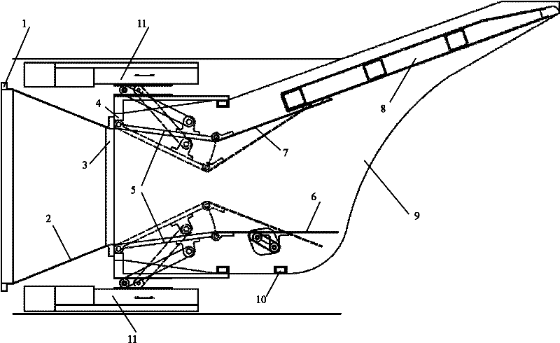
[0020] The nozzle scheme diagram according to an embodiment of the present invention is shown in figure 1 , the nozzle includes a front mounting edge (1), a circular torque transition section (2), a rear mounting edge (3), a rotating piece fixing casing (4), an upper / lower convergence adjustment plate (5), a lower web ( 6), adjustable upper web (7), fixed upper web (8), left / right side panels (9), support beams (10) and stepping motors (11), etc.

[0021] Actuation system

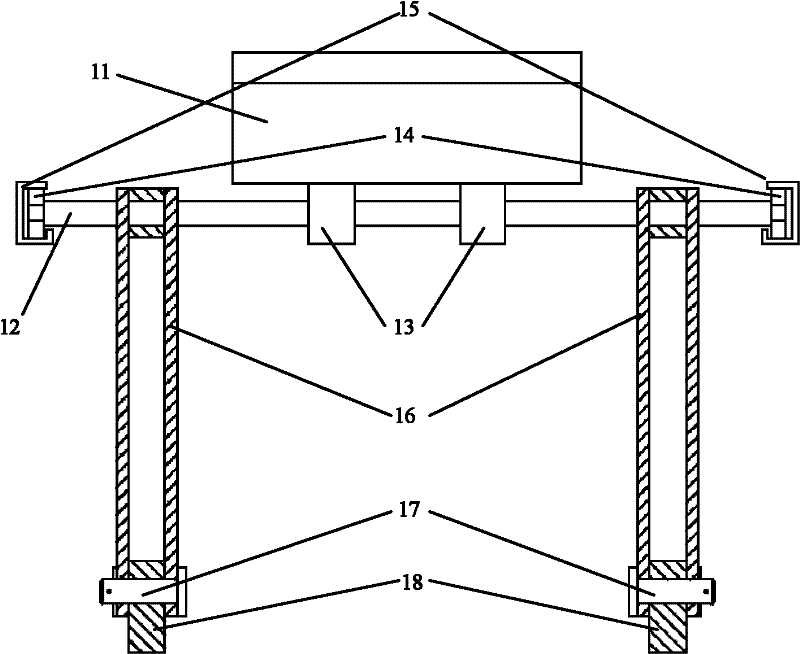
[0022] Such as figure 2 As shown, the actuation system according to one embodiment of the present invention includes a stepper motor (11), a stepped shaft (12), a mounting seat (13), a miniature bearing (14), a fixed channel (15) and a double-ended pull rod (16), wherein the stepper motor (11) transmits the axial displacement to the stepped shaft (12) through the mounting seat (13) connected thereto, and the stepped shaft (12) drives the miniature bearing (14) while doing axial movement Roll on fixed ch...


PUM


Abstract

The invention provides a differential adjustable unilateral expansion nozzle. In the invention, a nozzle throat area is bilaterally adjustable and differential adjustment can be carried out to ensure that an engine flow variation requirement is satisfied in a whole flight envelope; an nozzle exit area is adjustable to ensure that a gas ideal complete expansion requirement can be satisfied in a certain flight Mach number range; and the upper web of a nozzle is divided into an adjustable upper web and a fixed upper web between which a certain gap exists and the after body of an aircraft can be directly utilized by the fixed upper web so that that the operating force of a movement mechanism can be reduced. A boundary layer discharged from a front fuselage can be injected into the fixed upperweb through the gap under the flight conditions of transonic speed and low supersonic speed; and therefore, the wall static pressure of the fixed upper web is increased, the thrust loss caused by airflow overexpansion is decreased, meanwhile, the pitching moment of the aircraft is reduced and the nozzle is ensured to always achieve a higher thrust coefficient in the broad flight envelope, in addition, the cooling of the fixed upper web can be strengthened and the thermal load and the infrared signal characteristic of the nozzle are reduced.

Description

technical field [0001] The invention relates to a differential adjustable unilateral expansion nozzle. technical background [0002] Hypersonic vehicles are hailed as the third "revolution" in world aviation history after propellers and jet aircraft, and are also the technological commanding heights in the aerospace field in the 21st century. Research on hypersonic vehicles is forward-looking, strategic and driving. It will have an immeasurable and far-reaching impact on the military, economy and human social civilization. [0003] Power plant is the main key technology to realize hypersonic flight. In order to take into account the comprehensive requirements of safety, economy and combat effectiveness, the flight envelope of a hypersonic vehicle powered by an air-breathing engine is very wide (height is 0-40km or higher, and the Mach number of the aircraft ranges from subsonic, transonic, supersonic to hypersonic), which requires an integrated design of the vehicle / propul...

Claims


Application Information

Patent Timeline
IPC IPC(8): F02K1/11
Inventor 金捷谭杰季鹤鸣杜刚岳明王慧汝
Owner BEIHANG UNIV
Learn More