
Rocket motor nozzle throat area control system and method

a control system and rocket motor technology, applied in the field of solid rocket motors, can solve the problems of increasing burn rate, concomitant thrust generation of rocket motors, and many tactical missiles using solid rocket motors with relatively high burn rate, so as to achieve less expensive and not significantly affect overall motor efficiency

Inactive Publication Date: 2005-12-29
HONEYWELL INT INC
View PDF25 Cites 15 Cited by
  • Summary
  • Abstract
  • Description
  • Claims
  • Application Information

AI Technical Summary

Benefits of technology

This patent describes a way to control how well a rocket engine's nozzle allows air to escape from it without hurting its performance or being too costly compared to other options.

Problems solved by technology

The technical problem addressed in this patent text relates to finding a better ways to control the effectiveness of the flow area at the nozzle throat of a rocket motor without negatively impacting its overall efficiency and requiring expensive components and controls. Existing solutions involve either reducing the amount of combustion gas being released into the atmosphere (which reduces thrust) or increasing the complexity and expense of the entire system.

Method used


Image

  • Rocket motor nozzle throat area control system and method
  • Rocket motor nozzle throat area control system and method
  • Rocket motor nozzle throat area control system and method

Examples


Embodiment Construction

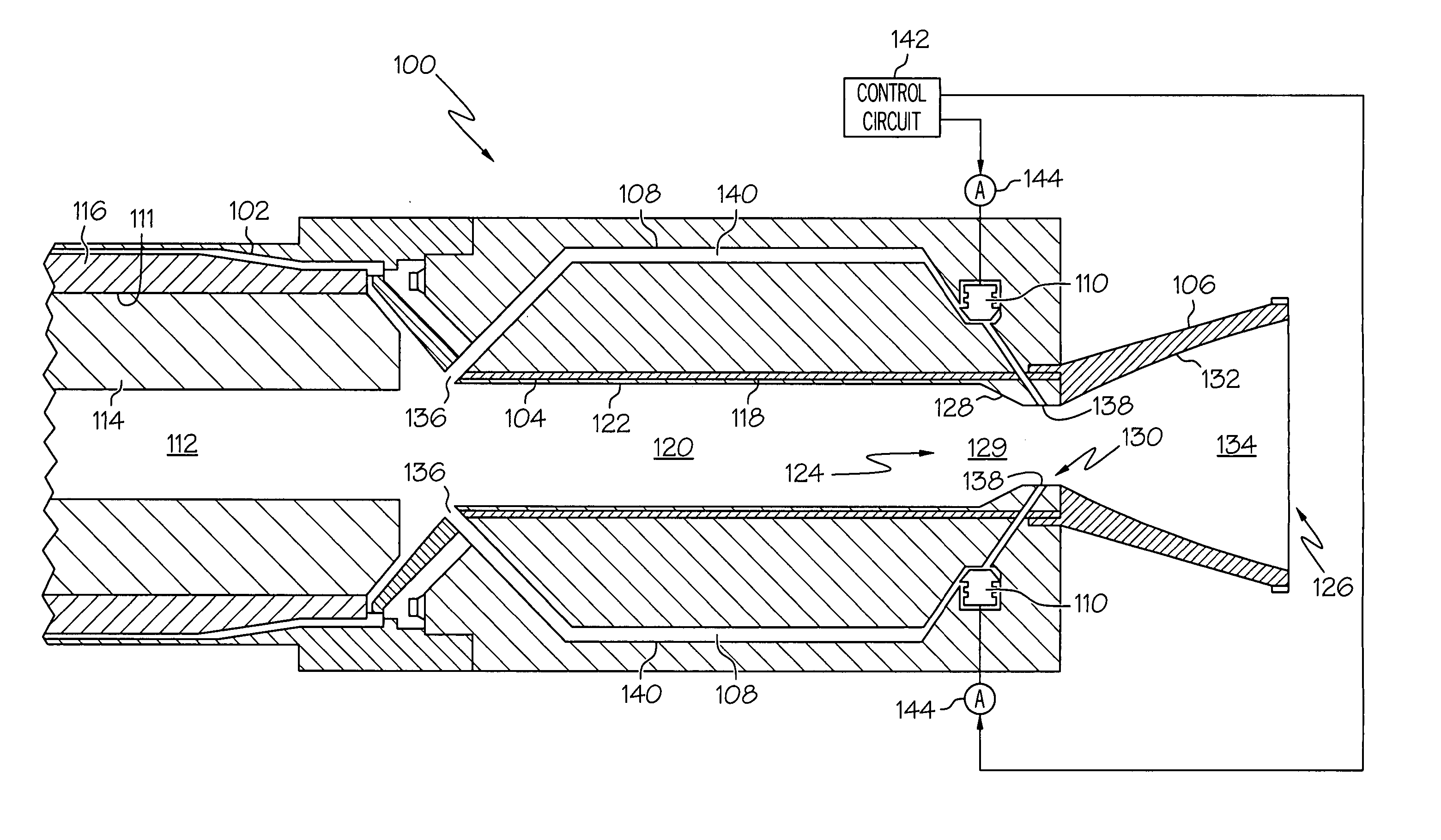
[0017] The following detailed description is merely exemplary in nature and is not intended to limit the invention or its application and uses. Furthermore, there is no intention to be bound by any theory presented in the preceding background or the following detailed description. In this regard, before proceeding with the detailed description, it will be appreciated that the present invention is not limited to use with a particular type or configuration of rocket motor. Thus, although the embodiments are described as being implemented in a rocket motor that includes a blast tube, it will be appreciated that the embodiments could also be implemented in rocket motor that does not include a blast tube.

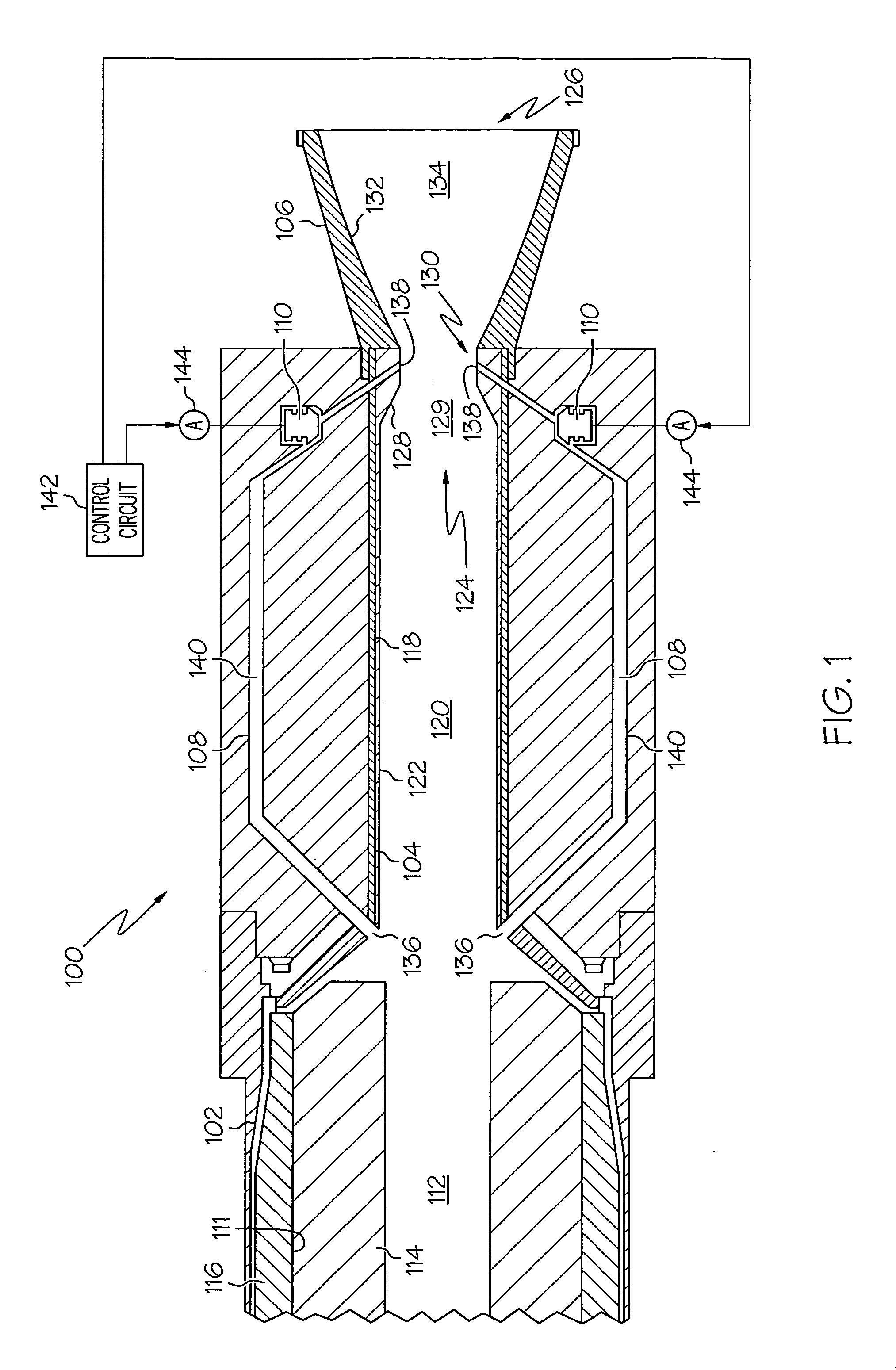
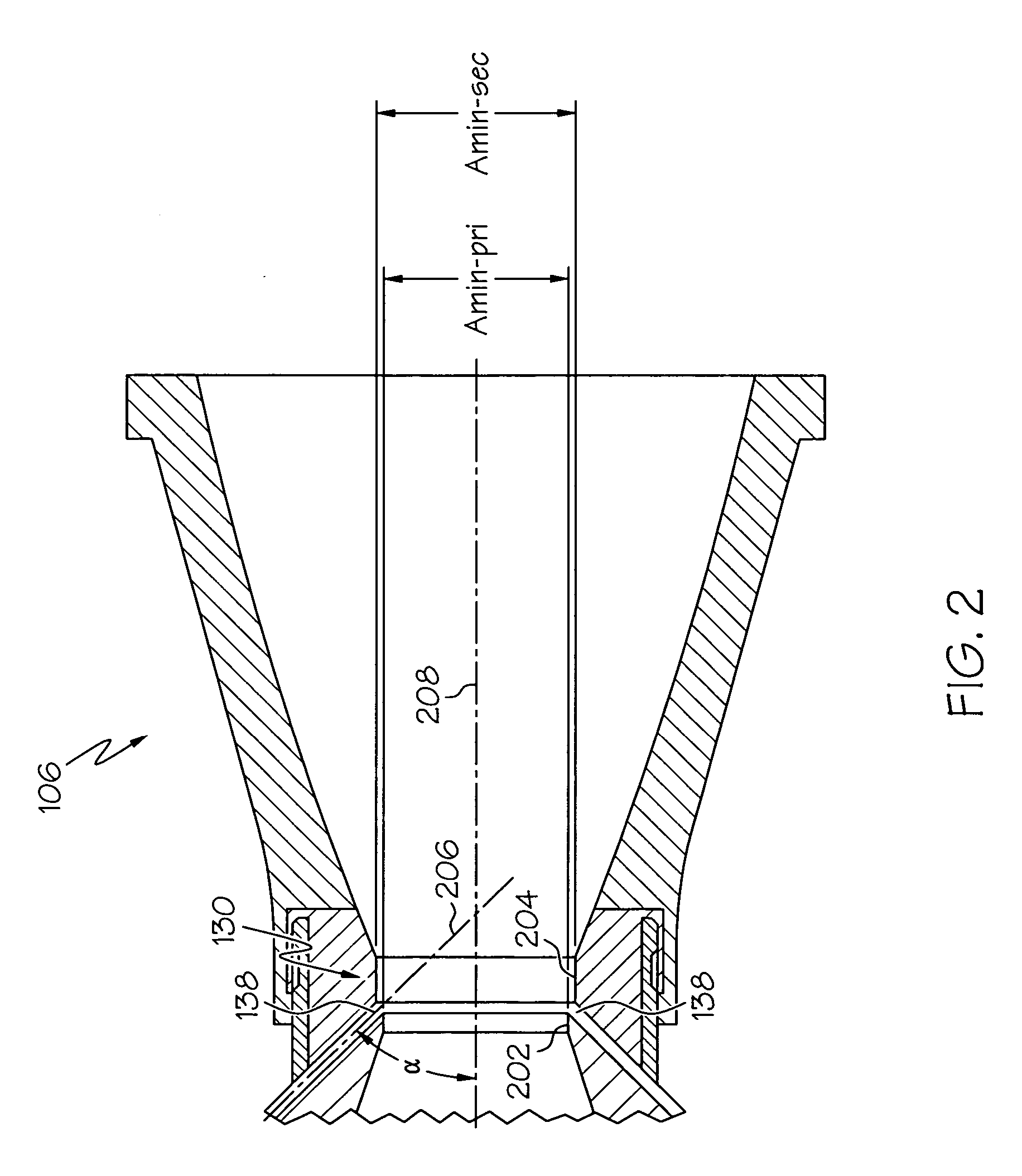
[0018] A simplified cross section view of an exemplary embodiment of a solid rocket motor 100 is shown in FIG. 1. The solid rocket motor 100 includes a motor case 102, a blast tube 104, a nozzle 106, a plurality of injection ducts 108, and a plurality of control valves 110. The motor ca...


PUM


Abstract

A solid rocket motor including a combustion chamber, in which propellant is ignited to produce combustion gas, and a nozzle having a throat with an effective flow area, implements a system and method to inject gas into the nozzle throat to control its effective cross sectional flow area. Controlling the effective cross sectional flow area of the nozzle throat in turn controls combustion chamber pressure, thus the burn rate of the propellant in the combustion chamber, and thus the thrust generated thereby.

Description


Claims


Application Information

Patent Timeline
Owner HONEYWELL INT INC
Learn More