
An apparatus for temporary male contraception

A temporary, device technology used in the field of male contraceptive systems and devices

Active Publication Date: 2011-11-16
IMPLANTICA PATENT LTD
View PDF5 Cites 4 Cited by
  • Summary
  • Abstract
  • Description
  • Claims
  • Application Information

AI Technical Summary

Problems solved by technology

However, even if this technique presents the reverse possibility, individual fertility is associated with some side effects (e.g. formation of sperm antibodies)

Method used


Image

  • An apparatus for temporary male contraception
  • An apparatus for temporary male contraception
  • An apparatus for temporary male contraception

Examples


Embodiment Construction

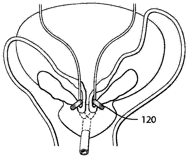
[0051] Figure 1A yes Figure 1B Schematic representation of the device for male contraception shown. Figure 1BApparatus 100 of FIG. 10 shows the restriction of the vas deferens 200A, 200B downstream of the ampulla of the vas deferens 220A, 220B. Thus, the device is operable to temporarily prevent access to the urethra and provide time-limited sterility. The instrument 100 has a restriction device 120 adapted to mechanically or hydraulically compress the vas deferens and a control device 150 for Controls the operation of the restraint device. The control device 150 is located subcutaneously and includes an outer part and an inner part. The energy supplier unit (energy transmitting device) 180 is capable of wirelessly transmitting (transmitting to the energy conversion device 151 ) the energy supply device, and the energy conversion device 151 is connected with the energy source 152 for supplying energy to the energy consumption parts of the apparatus. The external remote...


PUM


Abstract

The present invention relates to a male contraception apparatus for obtaining temporary sterility of a male mammalian individual. The apparatus comprises an implantable restriction device adapted to restrict vas deference in the region downstream the ampulla during a controlled period in order to preventing sperms to reach the urethra. Further, the apparatus comprises a control device for controlling the operation of the restriction device.

Description

technical field [0001] In general, the present invention relates to systems and devices for male contraception which operates by closing the vas deferens for a controlled temporary period. Background technique [0002] The usual route of male contraception is the occlusion of the vas deferens (sperm transport channel). A vasectomy is the surgical removal of the vas deferens and is usually limited to permanent infertility. More recently, other options have become available by providing devices that will be inserted into the vas deferens and obtain a sealing effect. US Patent No. 6513528 describes one such technique involving a set of silicone plugs for insertion into the vas deferens. However, even if this technique presents the reverse possibility, individual fertility is associated with some side effects such as the formation of sperm antibodies. Therefore, there is a need for more gentle techniques for controlled male contraception that allow for ambivalence with minima...

Claims


Application Information

Patent Timeline
Patent Type & Authority Applications(China)
IPC IPC(8): A61F6/20A61B17/12A61N1/36
CPCA61F2250/0001A61F6/206A61N1/3787A61N1/0551A61F5/0059A61F6/02A61N1/36007
Inventor 彼得·福塞尔
Owner IMPLANTICA PATENT LTD
Learn More