
Signal detecting method and device with function of temperature compensation for high-accuracy optical fiber gyroscope

A technology of fiber optic gyroscope and temperature compensation, which is applied in the direction of measuring devices, Sagnac effect gyroscopes, instruments, etc., and can solve problems such as constraints, zero bias of fiber optic gyroscopes, and repeatability variation of full temperature scale factors for bias stability , to achieve the effect of solving repeatability variation, improving temperature environment performance, and optimizing detection scheme

Inactive Publication Date: 2011-11-16
BEIHANG UNIV
View PDF1 Cites 30 Cited by
  • Summary
  • Abstract
  • Description
  • Claims
  • Application Information

AI Technical Summary

Problems solved by technology

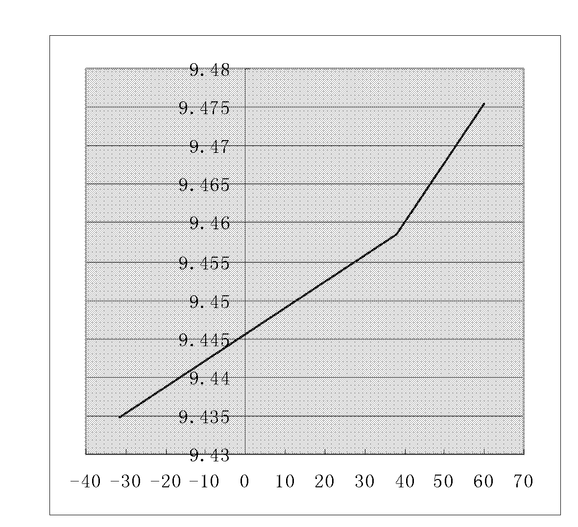
However, due to the wavelength λ of the light source, the geometric parameters D and L of the quartz fiber coil are more sensitive to the ambient temperature, resulting in the repetition of the zero bias, zero bias stability, and full temperature scaling factor after the key performance parameters of the fiber optic gyroscope are affected by the ambient temperature change. Poor performance, which restricts its practical application
[0004] At present, there is no mechanism to solve the effect of temperature on the performance of fiber optic gyroscope in the existing technology. How to improve the temperature characteristics of high-precision fiber optic gyroscope is a key technical problem that needs to be solved urgently.

Method used


Image

  • Signal detecting method and device with function of temperature compensation for high-accuracy optical fiber gyroscope
  • Signal detecting method and device with function of temperature compensation for high-accuracy optical fiber gyroscope
  • Signal detecting method and device with function of temperature compensation for high-accuracy optical fiber gyroscope

Examples


Embodiment Construction

[0034] The technical solutions in the embodiments of the present invention will be clearly and completely described below in conjunction with the accompanying drawings in the embodiments of the present invention. Obviously, the described embodiments are only some of the embodiments of the present invention, not all of them. Based on the embodiments of the present invention, all other embodiments obtained by persons of ordinary skill in the art without making creative efforts belong to the protection scope of the present invention.

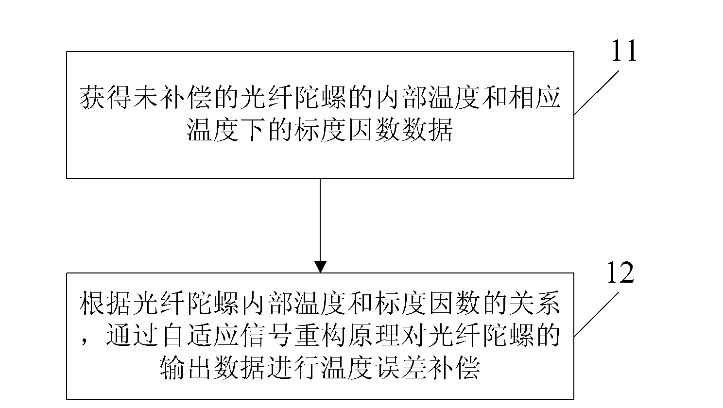
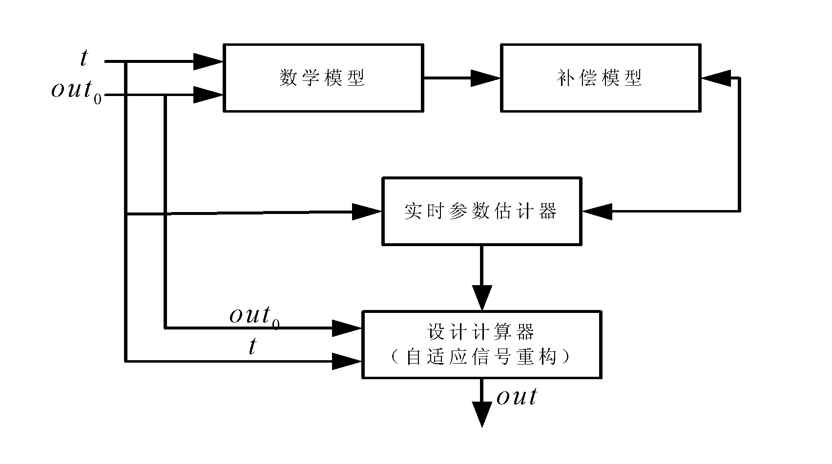
[0035] The embodiment of the present invention solves the problem that the repeatability of the full temperature scale factor of the fiber optic gyroscope becomes poor due to temperature changes by analyzing the relationship between the output data of the fiber optic gyroscope and the temperature, and using the principle of adaptive signal reconstruction to reconstruct the output data of the fiber optic gyroscope according to the temperature model. ...


PUM


Abstract

The embodiment of the invention discloses a signal detecting method and device with a function of temperature compensation for a high-accuracy optical fiber gyroscope. The method comprises the following steps: acquiring internal temperature of an uncompensated optical fiber gyroscope and scale factor data at corresponding temperature, and establishing the relationship between the internal temperature and the scale factor at the corresponding temperature; and performing temperature compensation on output data of the optical fiber gyroscope through an adaptive signal reconstruction principle according to the established relationship between the internal temperature of the optical fiber gyroscope and the scale factor. By analyzing the relationship of output data and temperature of the optical fiber gyroscope, output data of the optical fiber gyroscope is reconstructed according to a temperature model on the basis of the adaptive signal reconstruction principle, so that the problem that temperature changes causes poor repetitiveness of total temperature scale factors of the optical fiber gyroscope is solved, the digital signal detection scheme is optimized, the temperature environmental performance of the optical fiber gyroscope is improved, and the device has important magnificence for the engineering of the high-accuracy optical fiber gyroscope.

Description

technical field [0001] The invention relates to the technical field of fiber optic gyroscopes, in particular to a digital signal detection method and device with temperature compensation for high-precision fiber optic gyroscopes. Background technique [0002] At present, the interferometric fiber optic gyroscope is a new type of high stability angular velocity sensor developed with the development of fiber optic sensing technology. It has the advantages of no rotating parts, no preheating, simple structure, wide dynamic range, short start-up time, strong anti-electromagnetic interference and anti-vibration impact, low manufacturing cost, small size, light weight, low power consumption, etc., so it is widely used in inertial equipment is quite competitive. At present, compared with the technology of high-precision fiber optic gyroscopes at home and abroad, the gap in environmental performance is particularly prominent. These gaps greatly limit the practical level of high-pre...

Claims


Application Information

Patent Timeline
IPC IPC(8): G01C25/00G01C19/72
Inventor 李慧李立京毕兰张春熹
Owner BEIHANG UNIV
Learn More