Eureka AIR delivers breakthrough ideas for toughest innovation challenges, trusted by R&D personnel around the world.

Inertial/magnetic measurement device

a magnetic field and measurement device technology, applied in surveying, navigation, instruments, etc., can solve problems such as significant deformation of accuracy, noise-related errors, and small initial error caused by drift and nois

Active Publication Date: 2009-09-08
GENERAL ATOMICS
View PDF8 Cites 127 Cited by
  • Summary
  • Abstract
  • Description
  • Claims
  • Application Information

AI Technical Summary

Problems solved by technology

All IMU's experience noise-related errors from the accelerometers and gyros.
The initial error caused by the drift and noise can be quite small.
When these errors are incorporated into integrated real time data over a period of time, however, accuracy can degrade significantly.
McCall does not disclose, however, the manner in which the magnetic data is used.
The limitation of this approach to magnetic heading derivation is that roll and pitch estimation is highly dependent on “stillness” of the vehicle as well as the requirement of a gravity-only environment.
In “non-still” environments, disturbances caused by non-gravitational forces on the vehicle, can significantly corrupt the roll and pitch estimation accuracy.
In pure ballistic (free-fall) environments, gravitational acceleration is unobservable.

Method used


Image

  • Inertial/magnetic measurement device
  • Inertial/magnetic measurement device
  • Inertial/magnetic measurement device

Examples


Embodiment Construction

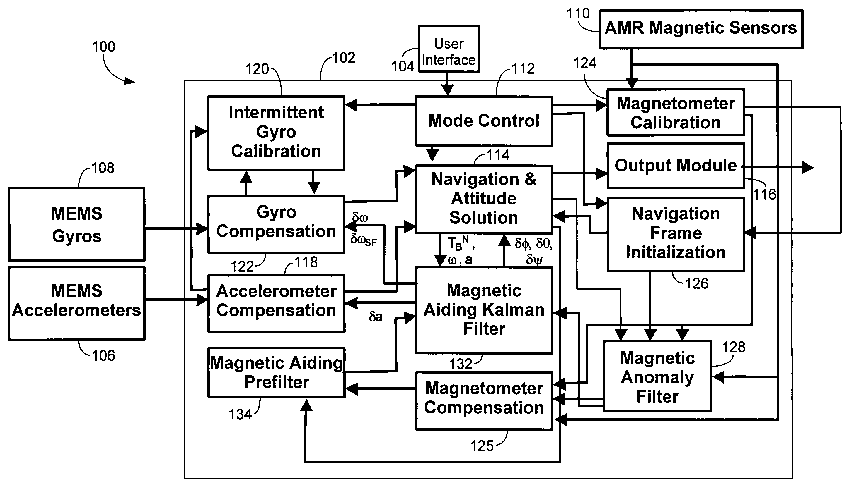
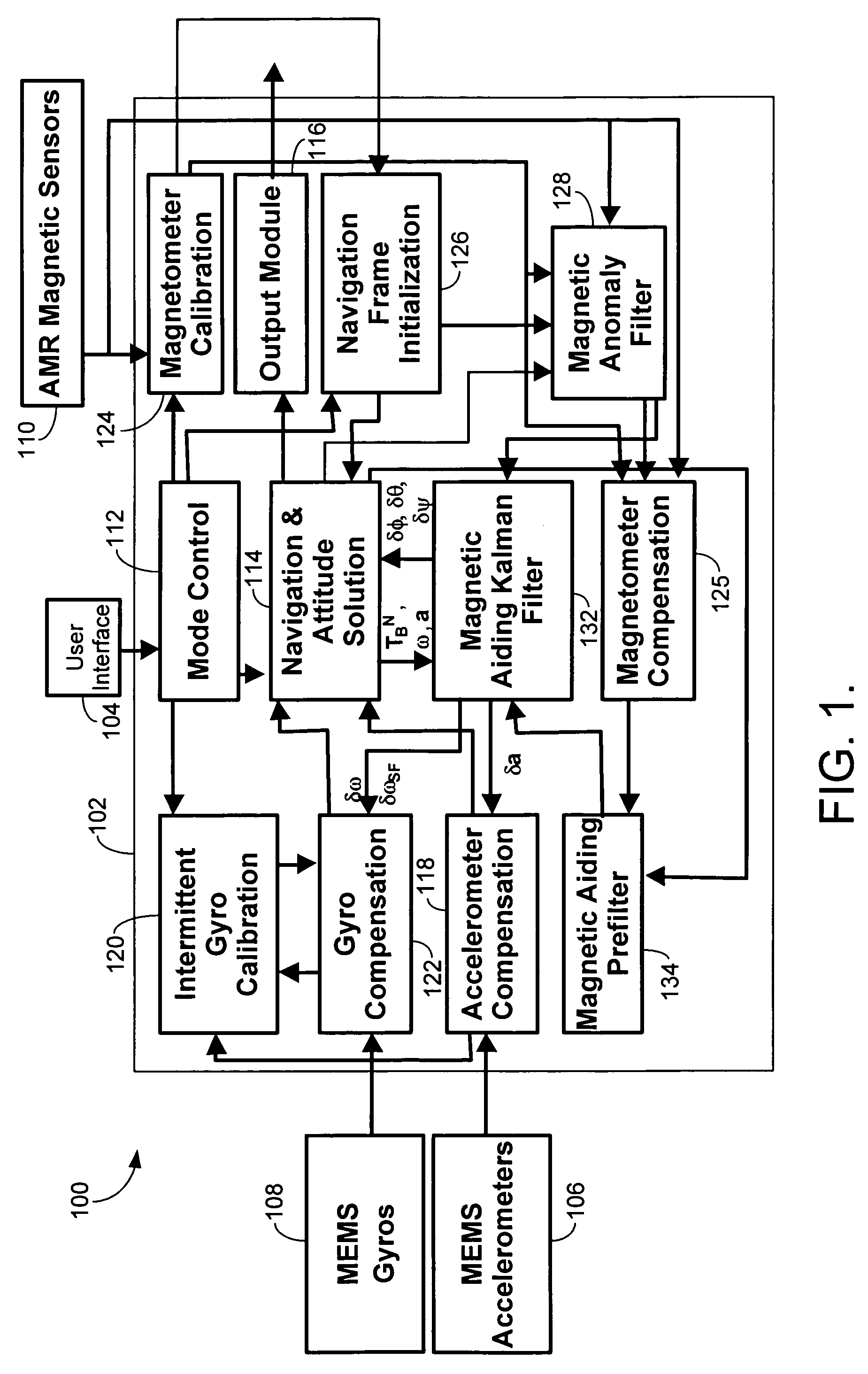
[0025]The present invention provides a system and method for onboard optimal estimation of heading, pitch, and roll through real-time measurement of magnetic field, acceleration and angular motion in three dimensions. More specifically, the invention relates to the use of magnetically-aided IMU's (i.e., inertial / magnetic measurement units) in dynamic environments.

[0026]The process uses the earth's magnetic field and inertial measurements to provide accurate onboard estimates of heading, pitch, and roll. This improves the prior art systems where only heading error is bound by magnetic aiding. Thus, a device used according to these processes does not have to continually rely on accelerometer data to get roll and pitch (only in remote instances in which either roll or pitch are magnetically unobservable for long periods).

[0027]Further, initialization of this system does not necessarily require prior or stored information of the local earth magnetic field (e.g., a geomagnetic map). This...


PUM


Abstract

Disclosed is a system and method for onboard optimal estimation of heading, pitch, and roll through real-time measurement of magnetic field, acceleration and angular motion in three dimensions. Magnetometer information is used to create an initial reference from which movement is measured. Thus, the process does not have to start when the body is in a known position. Further, the device does not have to continually rely on accelerometer data to get roll and pitch. To do this magnetic field data is used to complement gyro information. The magnetic data is used to estimate pitch, roll, and heading.

Description

CROSS-REFERENCE TO RELATED APPLICATIONS[0001]None.STATEMENT REGARDING FEDERALLY SPONSORED RESEARCH OR DEVELOPMENT[0002]None.BACKGROUND OF THE INVENTION[0003]1. Field of the Invention[0004]The invention relates to the measurement of linear and angular motion with magnetic field in three dimensions. More specifically, the invention relates to the use of inertial / magnetic measurement devices in highly dynamic environments without the necessity of known location and local geomagnetic field for applications that only need angular position of one component relative to another (e.g., fire arm night scope relative to night vision goggles) while providing magnetically aided attitude (angular orientation) output.[0005]2. Description of the Related Art[0006]An inertial measurement unit (IMU) is a single device which is associated with a vehicle or other body. The device collects a combination of angular and linear acceleration data which is then sent to a processor. Two kinds of groups of sens...

Claims


Application Information

Patent Timeline
Patent Type & Authority Patents(United States)
IPC IPC(8): G01C21/00
CPCG01C21/165G01C21/1654
Inventor WELLS, RANDY
Owner GENERAL ATOMICS
Why Eureka
Eureka Blog
Learn More