
Method for drawing columns and enlarging distances after replacing beams at high altitude in industrial factory building

A technology for industrial workshops and workshops, applied in building maintenance, construction, building construction, etc., can solve the problems of long construction period, many support measures, and large production impact, reduce the materials used for support and reinforcement measures, reduce construction costs, The effect of improving construction quality

Active Publication Date: 2011-11-16
MCC5 GROUP CORP SHANGHAI
View PDF3 Cites 6 Cited by
  • Summary
  • Abstract
  • Description
  • Claims
  • Application Information

AI Technical Summary

Problems solved by technology

Among these two methods, the former has a long construction period, which will cause a certain period of production shutdown and has a greater impact on production, while the latter has more support measures, and a large number of temporary measures materials and large machinery will be used in the implementation process, and the cost is relatively high. , at the same time, the security is poor
[0003] Therefore there are above-mentioned various inconveniences and problems in the known industrial plant transformation method

Method used


Image

  • Method for drawing columns and enlarging distances after replacing beams at high altitude in industrial factory building
  • Method for drawing columns and enlarging distances after replacing beams at high altitude in industrial factory building
  • Method for drawing columns and enlarging distances after replacing beams at high altitude in industrial factory building

Examples


Embodiment Construction

[0024] The present invention will be further described below in conjunction with embodiment and accompanying drawing.

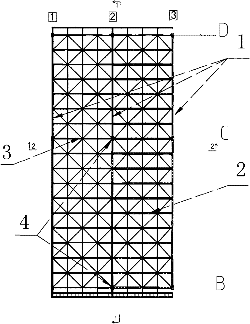
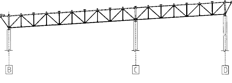
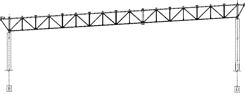
[0025] see now figure 1 , figure 2 and Figure 4 , figure 1 It is a schematic diagram of the roof steel structure system of an industrial plant, figure 2 before removing the pillar figure 1 1-1 view in and Figure 4 before removing the pillar figure 1 2-2 view in. As shown in the figure, the continuous casting workshop of a large steel factory needs to remove the reinforced concrete column (4) with a small steel column connected to the joist at the top of the column to expand the horizontal column and The project needs to change the column spacing of the original plant from 12m to 24m to add a 6-strand continuous casting machine facility.

[0026] Adopting the method for extracting columns and expanding distance after changing the beam at the high vacancy of the industrial factory building of the present invention, the following steps are specifi...


PUM


Abstract

The invention relates to a method for drawing columns and enlarging distances after replacing beams at high altitude in an industrial factory building. The method comprises the following steps: 1) under the condition of maintaining small capital steel columns of to-be-removed reinforced concrete columns of the industrial factory building, locally removing the upper roof from a roof truss joist of the industrial factory building and then removing an original roof truss upright joist in sections; 2) preparing a new reinforcing joist in two sections according to the length of the original roof truss upright joist; 3) hoisting the new reinforcing joist in sections, welding the new reinforcing joist with the small capital steel columns of the columns on two sides of the industrial factory building after placing the new reinforcing joist in position, and then separating the to-be-removed small capital steel columns of the industrial factory building from the original columns, arranging end plates at bottoms of the small capital steel columns of the columns on the two sides of the industrial factory building, and arranging reinforcing rib plates at the joint parts of the small capital steel columns and the upright joist; and 4) after removing a crane beam from the original reinforced concrete columns, removing the original reinforced concrete columns, recovering the roof and mounting a new crane beam.

Description

technical field [0001] The invention relates to a partial reconstruction method of an industrial factory building with a steel structure roof, in particular to a method for extracting columns and extending the distance after changing beams at high vacant positions of the industrial factory building. Background technique [0002] Many industrial workshops with steel roofs, the original design workshop steel column or reinforced concrete column spacing is generally only 6m, 12m, with the technical transformation of the factory, equipment upgrades, enterprises use the original factory building to add new equipment and expand production capacity. To achieve leapfrog development, the local column spacing of the original factory building needs to be changed from 6m to 12m or from 12m to 24m. Generally, there are two methods for reconstruction. One method is to remove all steel structures and driving beams on the roof first, remove the steel columns or reinforced concrete columns a...

Claims


Application Information

Patent Timeline
IPC IPC(8): E04G23/02
Inventor 郭魁祥李文李长明李春贺王海龙
Owner MCC5 GROUP CORP SHANGHAI
Learn More